Gigabyte MZJ19AI driver and firmware
Related Gigabyte MZJ19AI Manual Pages
Download the free PDF manual for Gigabyte MZJ19AI and other Gigabyte manuals at ManualOwl.com
Manual - Page 3
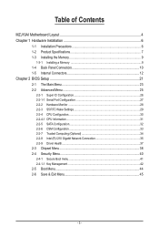
... 7 1-3 Installing the Memory 9
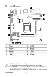
1-3-1 Installing a Memory 9 1-4 Back Panel Connectors 10 1-5 Internal Connectors 12
Chapter 2 BIOS Setup 21 2-1 The Main Menu 23 2-2 Advanced Menu 25
2-2-1 Super IO Configuration 26 2-2-1-1 Serial Port Configuration 27 2-2-2 Hardware Monitor 28 2-2-3 S5 RTC Wake Settings 29 2-2-4 CPU Configuration 30 2-2-4-1 CPU Information...31 2-2-5 SATA Configuration...
Manual - Page 6
... a motherboard, CPU or memory. If you do not have an ESD wrist strap, keep your hands dry and first touch a metal object to eliminate static electricity. • Prior to installing the motherboard, please have it on top of an antistatic pad or within an electrostatic shielding container. • Before unplugging the power supply cable from the motherboard, make...
Manual - Page 7
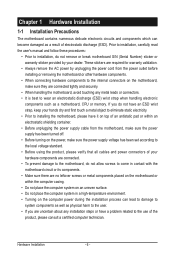
... ATX power connector 1 x SATA 3Gb/s connector 4 x SATA 6Gb/s connector 1 x CPU fan header 1 x System fan header 1 x Front panel header 1 x Front Panel Audio header 1 x USB 2.0 header 1 x TPM module connector 1 x GPIO connector 1 x Speaker out header 1 x VGA port 1 x Serial port 1 x HDMI port 1 x USB3.0 port 1 x eSATA port 2 x USB 2.0 ports 2 x RJ-45 ports 2 x Audio connectors
I/O Controller Š...
Manual - Page 8
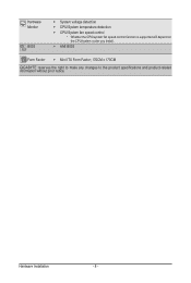
...;Š System voltage detection ŠŠ CPU/System temperature detection ŠŠ CPU/System fan speed control * Whether the CPU/system fan speed control function is supported will depend on
the CPU/system cooler you install.
ŠŠ AMI BIOS
Form Factor ŠŠ Mini ITX Form Factor; 170CM x 170CM GIGABYTE reserves the right to make any changes to the...
Manual - Page 9
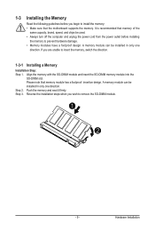
... you begin to install the memory: • Make sure that the motherboard supports the memory. It is recommended that memory of the
same capacity, brand, speed, and chips be used. • Always turn off the computer and unplug the power cord from the power outlet before installing
the memory to prevent hardware damage. • Memory modules have a foolproof design. A memory module can be...
Manual - Page 10
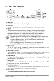
... Setup, then set Onboard VGA output connect to D-SUB/ HDMI under Advanced BIOS Features..
• Please note the HDMI audio output only supports AC3, DTS and 2-channel-LPCM formats. (AC3 and DTS require the use of an external decoder for decoding.)
USB 3.0 Port The USB port supports the USB 3.0 specification. Use this port for USB devices such as a USB keyboard/mouse, USB printer, USB flash drive...
Manual - Page 11
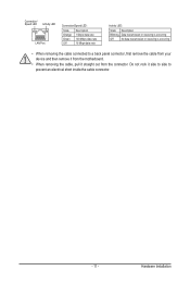
... receiving is occurring
Off
No data transmission or receiving is occurring
• When removing the cable connected to a back panel connector, first remove the cable from your device and then remove it from the motherboard.
• When removing the cable, pull it straight out from the connector. Do not rock it side to side to...
Manual - Page 12
... connectors you wish to connect.
• Before installing the devices, be sure to turn off the devices and your computer. Unplug the power
cord from the power outlet to prevent damage to the devices.
• After installing the device and before turning on the computer, make sure the device cable has
been securely attached to the connector on the motherboard.
Hardware Installation
- 12 -
Manual - Page 13
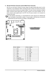
... on the motherboard. Before connecting the power connector, first make sure the power supply is turned off and all devices are properly installed. The power connector possesses a foolproof design. Connect the power supply cable to the power connector in the correct orientation. The 12V power connector mainly supplies power to the CPU. If the 12V power connector is not connected, the computer will...
Manual - Page 14
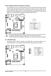
... the ground wire). The motherboard supports CPU fan speed control, which requires the use of a CPU fan with fan speed control design. For optimum heat dissipation, it is recommended that a system fan be installed inside the chassis.
CPU_FAN
SYS_FAN
1
Pin No. 1 2 3 4
Definition GND +12V Sense Speed Control
• Be sure to connect fan cables to the fan headers to...
Manual - Page 15
... PORT
RXN
DEBUG
RXP
PORT
P5V
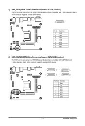
6) SATA1/SATA5 (SATA 6Gb/s Connectors/Support SATA DOM Function) The SATA connectors conform to SATA 6Gb/s standard and are compatible with SATA 3Gb/s and 1.5Gb/s standard. Each SATA connector supports a single SATA device.
SATA3 SATA4
SATA1 SATA2
1
77
1
1
77
1
Pin No. 1 2 3 4 5 6 7
Definition GND TXP TXN GND RXN RXP GND
- 15 -
Hardware Installation
Manual - Page 16
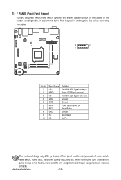
... below. Note the positive and negative pins before connecting the cables.
2
10
1
9
Pin No. 1 2 3 4 5 6 7 8 9 10
Signal Name HD+ MPD+ HD- GND GND PW+ RST+ GND NC NC
Definition Hard Disk LED Signal anode (+) Power LED Signal anode (+) Hard Disk LED Signal cathode(-) Ground Ground Power Button anode (+) Reset Button Ground No connect No Pin
The...
Manual - Page 19
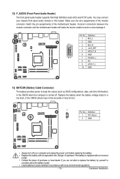
... motherboard header will make the device unable to work or even damage it.
Pin No. Definition
1 MIC_L
2 GND
21
3 MIC_R
4 -ACZ_DET
5 HPOUT_R
6 GND
10 9
7 FAUDIO_J
8 NC
9 HPOUT_L
10 GND
13) BATCON (Battery Cable Connector)
The battery provides power to keep the values (such as BIOS configurations, date, and time information) in the CMOS when the computer...
Manual - Page 20
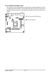
... BIOS configurations) and reset the CMOS values to factory defaults. To clear the CMOS values, place a jumper cap on the two pins to temporarily short the two pins or use a metal object like a screwdriver to touch the two pins for a few seconds.
Open: Normal operation (Default setting)
Close: Clear CMOS data
Hardware Installation...
Manual - Page 24
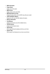
... Display name of the project. BIOS Version Display version number of the BIOS. BIOS Build Date and Time Displays the date and time when the BIOS setup utility was created. LAN1/LAN2 MAC Address Displays the LAN1 and LAN2 MAC address information. Memory Information Total Memory Display the total memory size of the installed memory. TXE FW Version Display the TXE firmware version. System Date Set...
Manual - Page 28
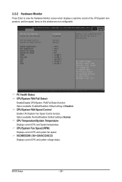
... setting is Disabled. CPU/System FAN Speed Control Enable CPU/System Fan Speed Control function. Option available: Normal/Disabled. Default setting is Normal. CPU Temperature/System Temperature Displays current CPU and System temperature. CPU/System Fan Speed (RPM) Displays current CPU and system fan speed. VCORE/DDR1.35/+12V/VCC/VCC3 Displays current CPU and system voltage status.
BIOS Setup...
Manual - Page 30
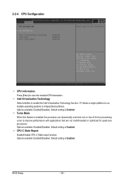
..., the processor can dynamically overclock one or two of its four processing cores to improve performance with applications that are not multi-threaded or optimized for quad-core processors. Options available: Enabled/Disabled. Default setting is Enabled. CPU C State Report
Enable/Disable CPU C State report function. Options available: Enabled/Disabled. Default setting is Enabled.
BIOS Setup
- 30...
Manual - Page 31
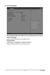
2-2-4-1 CPU Information
CPU Type/Signature/Microcode Path/Processor Cores/64-bit/Intel HT Technology/ Intel VT-x Technology Displays the technical specifications for the installed processor. Cache Information L1 Data Cache / L1 Code Cache / L2 Cache / L3 Cache Displays the technical specifications for the installed processor.
- 31 -
BIOS Setup
Manual - Page 32
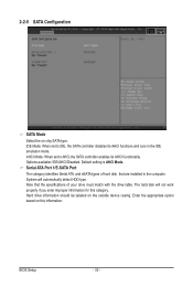
... AHCI,the SATA controller enables its AHCI functionality. Options available: IDE/AHCI/Disabled. Default setting is AHCI Mode. Serial ATA Port 1/E-SATA Port
The category identifies Serial ATA and eSATA types of hard disk that are installed in the computer. System will automatically detect HDD type. Note that the specifications of your drive must match with the drive table. The hard disk will not...
Manual - Page 37
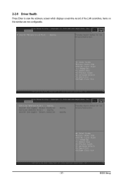
2-2-9 Driver Health
Press Enter to view the submenu screen which displays a real-time record of the LAN controllers, Items on this window are non-configurable.
- 37 -
BIOS Setup