HP Chromebook 14-q000 driver and firmware
Drivers and firmware downloads for this Hewlett-Packard item
Related HP Chromebook 14-q000 Manual Pages
Download the free PDF manual for HP Chromebook 14-q000 and other HP manuals at ManualOwl.com
Maintenance and Service Guide - Page 2
... constituting an additional warranty. HP shall not be liable for technical or editorial errors or omissions contained herein. First Edition: September 2013 Document Part Number: 741336-001 Product notice This guide describes features that are common to most models. Some features may not be available on your computer. Software terms By installing, copying, downloading, or otherwise using any...
Maintenance and Service Guide - Page 7
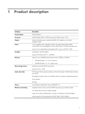
... Name Processor Chipset Panel
Graphics Memory
Mass storage device Audio and video
Sensor Wireless networking
Description HP Chromebook14 Intel® Celeron® 2955U 1.40-GHz processor (2.0-MB L3 cache, 15 W) Intel Lynx Point-LP processor controller hub (PCH), ULT, soldered on circuit (SoC), integrated in MCP 14.0-in, BrightView (BV), high-definition (HD), white light-emitting display (WLED...
Maintenance and Service Guide - Page 24
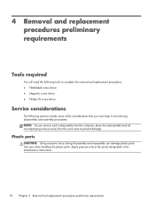
...; Magnetic screw driver ● Phillips P0 screw driver
Service considerations
The following sections include some of the considerations that you must keep in mind during disassembly and assembly procedures. NOTE: As you remove each subassembly from the computer, place the subassembly (and all accompanying screws) away from the work area to prevent damage.
Plastic...
Maintenance and Service Guide - Page 26
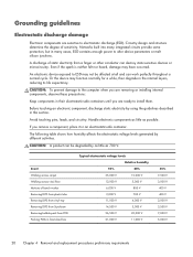
...Networks built into many integrated circuits provide some protection, but in many cases, ESD contains enough power to alter device...computer when you are removing or installing internal components, observe these precautions:
Keep components in their electrostatic-safe containers until you are ready to install... V
800 V
2,000 V
700 V
11,500 V
4,000 V
14,500 V
5,000 V
26,500 V
20,000 V
21,000 ...
Maintenance and Service Guide - Page 27
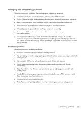
...properly grounded work surface and use properly grounded tools and equipment.
● Use conductive field service tools, such as cutters, screw drivers, and vacuums.
● When fixtures must directly contact dissipative surfaces, use fixtures made ...leads, or circuitry.
● Turn off power and input signals before inserting or removing connectors or test equipment.
Grounding guidelines
21
Maintenance and Service Guide - Page 31
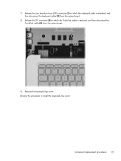
... (ZIF) connector (1) to which the keyboard cable is attached, and then disconnect the keyboard cable (2) from the system board.
8. Release the ZIF connector (3) to which the TouchPad cable is attached, and then disconnect the TouchPad cable (4) from the system board.
9. Remove the keyboard/top cover. Reverse this procedure to install the keyboard/top cover.
Component replacement procedures...
Maintenance and Service Guide - Page 33
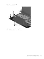
5. Remove the speakers (4). Reverse this procedure to install the speakers.
Component replacement procedures 27
Maintenance and Service Guide - Page 34
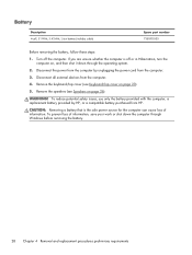
..., use only the battery provided with the computer, a replacement battery provided by HP, or a compatible battery purchased from HP.
CAUTION: Removing a battery that is the sole power source for the computer can cause loss of information. To prevent loss of information, save your work or shut down the computer through Windows before removing the battery.
28 Chapter...
Maintenance and Service Guide - Page 36
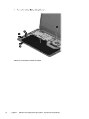
5. Remove the battery (5) by sliding it forward. Reverse this procedure to install the battery. 30 Chapter 4 Removal and replacement procedures preliminary requirements
Maintenance and Service Guide - Page 38
... system.
2. Disconnect the power from the computer by unplugging the power cord from the computer.
3. Disconnect all external devices from the computer.
4. Remove the keyboard/top cover (see Keyboard/top cover on page 23).
5. Disconnect the battery cable from the system board (see Speakers on page 26).
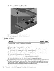
CAUTION: To prevent an unresponsive system, replace the wireless module only with...
Maintenance and Service Guide - Page 39
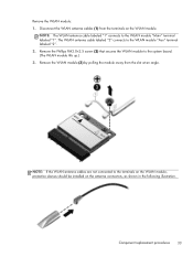
... the WLAN module to the system board. (The WLAN module tilts up.) 3. Remove the WLAN module (3) by pulling the module away from the slot at an angle.
NOTE: If the WLAN antenna cables are not connected to the terminals on the WLAN module, protective sleeves should be installed on the antenna connectors, as...
Maintenance and Service Guide - Page 40
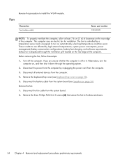
... then shut it down through the operating system.
2. Disconnect the power from the computer by unplugging the power cord from the computer.
3. Disconnect all external devices from the computer.
4. Remove the keyboard/top cover (see Keyboard/top cover on page 23).
5. Disconnect the battery cable from the system board (see Speakers on page 26).
Remove the fan:
1. Disconnect...
Maintenance and Service Guide - Page 41
... to install the fan.
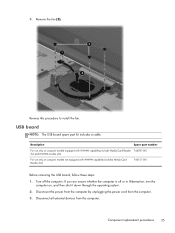
USB board
NOTE: The USB board spare part kit includes a cable.
Description
Spare part number
For use only on computer models equipped with WWAN capability (includes Media Card Reader 744781-001 slot and WWAN module slot)
For use only on computer models not equipped with WWAN capability (includes Media Card Reader slot)
740151-001
Before removing the USB board, follow...
Maintenance and Service Guide - Page 42
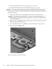
... 2. Release the ZIF connector (2) to which the USB board cable is attached, and then disconnect the USB board cable from the system board. 3. Remove the Phillips PM2.5×4.5 screw (3) that secures the USB board to the base enclosure. 4. Remove the USB board (4) and cable.
Reverse this procedure to install the USB board.
36 Chapter 4 Removal and replacement procedures preliminary requirements
Maintenance and Service Guide - Page 44
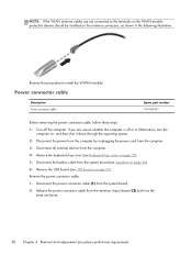
...Disconnect all external devices from the computer. 4. Remove the keyboard/top cover (see Keyboard/top cover on page 23). 5. Disconnect the battery cable from the system board (see Speakers on page 26). 6. Remove the USB board (see USB board on page 35). Remove the power connector cable: 1. Disconnect the power connector cable (1) from the system board. 2. Release the power connector cable from the...
Maintenance and Service Guide - Page 45
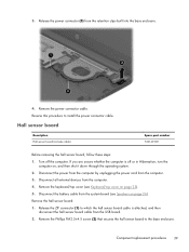
... external devices from the computer. 4. Remove the keyboard/top cover (see Keyboard/top cover on page 23). 5. Disconnect the battery cable from the system board (see Speakers on page 26). Remove the hall sensor board: 1. Release the ZIF connector (1) to which the hall sensor board cable is attached, and then
disconnect the hall sensor board cable from the USB board. 2. Remove...
Maintenance and Service Guide - Page 46
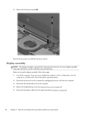
... then shut it down through the operating system. 2. Disconnect the power from the computer by unplugging the power cord from the computer. 3. Disconnect all external devices from the computer. 4. Remove the keyboard/top cover (see Keyboard/top cover on page 23). 5. Disconnect the battery cable from the system board (see Speakers on page 26).
40 Chapter 4 Removal and...
Maintenance and Service Guide - Page 57
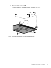
c. Remove the display panel cable (3). The display panel cable is available using spare part number 740145-001.
Reverse this procedure to reassemble and install the display assembly.
Component replacement procedures 51
Maintenance and Service Guide - Page 58
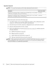
... UMA memory
Before removing the system board, follow these steps:
1. Turn off the computer. If you are unsure whether the computer is off or in Hibernation, turn the computer on, and then shut it down through the operating system.
2. Disconnect the power from the computer by unplugging the power cord from the computer.
3. Disconnect all external devices from the computer.
4. Remove...
User Guide - Page 2
... constituting an additional warranty. HP shall not be liable for technical or editorial errors or omissions contained herein.
First Edition: September 2013
Document Part Number: 741337-001
Product notice
This guide describes features that are common to most models. Some features may not be available on your computer.
Software terms
By installing, copying, downloading, or otherwise using any...