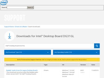
Intel DG31GL - Desktop Board Essential Series Motherboard driver and firmware
Drivers and firmware downloads for this Intel item
Related Intel DG31GL Manual Pages
Download the free PDF manual for Intel DG31GL and other Intel manuals at ManualOwl.com
Product Guide - Page 2
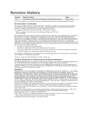
Revision History
Revision -001
Revision History First release of the Intel® Desktop Board DG31GL Product Guide
Date March 2008
If an FCC declaration of conformity marking is present on the board, the following statement applies:
FCC Declaration of Conformity
This device complies with Part 15 of the FCC Rules. Operation is subject to the following two conditions...
Product Guide - Page 3

...not be supported without further evaluation by Intel.
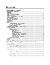
Document Organization
The chapters in this Product Guide are arranged as follows: 1 Desktop Board Features: a summary of product features 2 Installing and Replacing Desktop Board Components: instructions on how to install
the Desktop Board and other hardware components 3 Updating the BIOS: instructions on how to update the BIOS A Error Messages...
Product Guide - Page 5
...1 Desktop Board Features
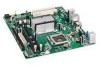
Desktop Board Components 11 Processor ...13 Main Memory...13 Intel® G31 Express Chipset 14 Audio Subsystem 15 Legacy Input/Output (I/O) Controller 15 LAN Subsystem 15 Hi-Speed USB 2.0 Support 16 Enhanced IDE Interface 17 Serial ATA...17 Expandability...17 BIOS ...17
Serial ATA and IDE Auto Configuration 17 PCI* and Auto Configuration 17 Security Passwords 18...
Product Guide - Page 6
Intel Desktop Board DG31GL Product Guide
Connecting the Diskette Drive Cable 35 Connecting the IDE Cable 36 Connecting the Serial ATA (SATA) Cables 38 Connecting to the Internal Headers and Connectors 39
Connecting to the Front Panel Audio Header 40 Connecting to the S/PDIF Connector 40 Connecting to the Serial Port Header 40 Connecting to the Alternate Front Panel Power LED Header 41 ...
Product Guide - Page 7

... Summary 9 2. Desktop Board DG31GL Components 12 3. LAN Connector LEDs 16 4. Front Panel Intel High Definition Audio Header Signal Names 40 5. S/PDIF Connector Signal Names 40 6. Serial Port Header Signal Names 40 7. Alternate Front Panel Power LED Header Signal Names 41 8. Front Panel Header Signal Names 41 9. USB 2.0 Header Signal Names 42 10. Jumper Settings for the BIOS Setup Program...
Product Guide - Page 10
Intel Desktop Board DG31GL Product Guide
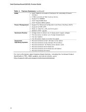
Table 1. Feature Summary (continued)
BIOS
• Intel® Platform Innovation Framework for extensible firmware interface
• 4-Mbit symmetrical flash memory device
• Support for SMBIOS
• Intel® Rapid BIOS Boot
• Intel® Express BIOS Update
Power Management • Support for Advanced Configuration and Power ...
Product Guide - Page 13
... for more information: • Instructions on installing or upgrading the processor, page 27 in Chapter 2 • Supported processors for Desktop Board DG31GL,
http://www.intel.com/go/findCPU
Main Memory
NOTE
To be fully compliant with all applicable Intel ® SDRAM memory specifications, the board should be populated with DIMMs that support the Serial Presence Detect (SPD) data structure...
Product Guide - Page 14
Intel Desktop Board DG31GL Product Guide
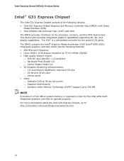
Intel® G31 Express Chipset
The Intel G31 Express Chipset consists of the following devices: • Intel G31 Express Chipset Graphics and Memory Controller Hub (GMCH) with Direct
Media Interface (DMI) • Intel 82801G I/O Controller Hub (ICH7) with DMI The GMCH provides interfaces to the processor, memory, and the DMI interconnect. This device ...
Product Guide - Page 15
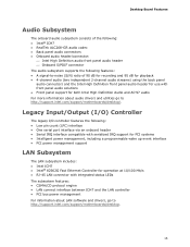
...; Intel® 82562G Fast Ethernet Controller for operation at 10/100 Mb/s • RJ-45 LAN connector with integrated status LEDs The subsystem features: • CSMA/CD protocol engine • LAN connect interface between ICH7 and the LAN controller • PCI bus power management For information about LAN software and drivers, go to http://support.intel.com/support/motherboards/desktop.
15
Product Guide - Page 16
...
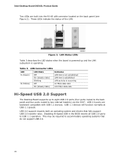
Hi-Speed USB 2.0 Support
The Desktop Board supports up to eight USB 2.0 ports (four ports routed to the back panel and four ports routed to two internal headers) via the ICH7. USB 2.0 ports are backward compatible with USB 1.1 devices. USB 1.1 devices will function normally at USB 1.1 speeds.
USB 2.0 support requires both an operating system and drivers that fully support USB 2.0 transfer rates...
Product Guide - Page 17
... devices (such as CD-ROM drives) • Older PIO Mode devices • Ultra DMA-33 and ATA-66/100 protocols
Serial ATA
The Desktop Board supports two Serial ATA channels (3.0 Gb/s) via ICH7, connecting one device per channel.
Expandability
For system expansion, the Desktop Board provides two PCI bus connectors.
BIOS
The BIOS provides the Power-On Self-Test (POST), the BIOS Setup program, the PCI...
Product Guide - Page 18
Intel Desktop Board DG31GL Product Guide
Security Passwords
The BIOS includes security features that restrict whether the BIOS Setup program can be accessed and who can boot the computer. A supervisor password and a user password can be set for the BIOS Setup and for booting the computer, with the following restrictions: • The supervisor password gives unrestricted access to view and change ...
Product Guide - Page 20
... Desktop Board supports the PCI Bus Power Management Interface Specification. Add-in cards that support this specification can participate in power management and can be used to wake the computer.
+5 V Standby Power Indicator LED
CAUTION If the AC power has been switched off and the standby power indicator is still lit, disconnect the power cord before installing or removing any devices connected...
Product Guide - Page 23
...I/O shield • Install and remove the Desktop Board • Install and remove a processor • Install and remove memory • Connect the diskette drive cable • Connect the IDE and Serial ATA cables • Connect to the internal headers and connectors • Connect to the audio system • Connect chassis fan and power supply cables • Set the BIOS configuration jumper...
Product Guide - Page 42
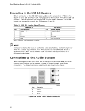
...Power (+5 V) DD+ Ground No Connection
NOTE Computer systems that have an unshielded cable attached to a USB port might not meet FCC Class B requirements, even if no device or a low-speed USB device is attached to the cable. Use a shielded cable that meets the requirements for a full-speed USB device.
Connecting to the Audio System
After installing the audio driver from the Intel Express Installer...
Product Guide - Page 45
....
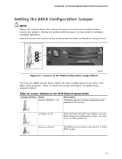
Table 10. Jumper Settings for the BIOS Setup Program Modes
Jumper Setting Mode Normal (default) (1-2)
Description
The BIOS uses the current configuration and passwords for booting.
Configure (2-3) Recovery (None)
After the Power-On Self-Test (POST) runs, the BIOS displays the Maintenance Menu. Use this menu to clear passwords.
The BIOS recovers data in the event of a failed BIOS update.
45
Product Guide - Page 53
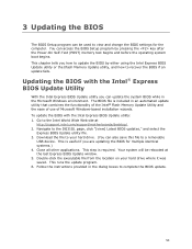
... Intel® Flash Memory Update Utility and the ease of use of Microsoft Windows-based installation wizards. To update the BIOS with the Intel Express BIOS Update utility: 1. Go to the Intel World Wide Web site at
http://support.intel.com/support/motherboards/desktop/. 2. Navigate to the DG31GL page, click "[view] Latest BIOS updates," and select the
Express BIOS Update utility file. 3. Download...
Product Guide - Page 54
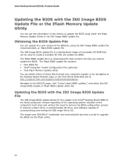
...; Intel Flash Memory Update Utility You can obtain either of these files through your computer supplier or by navigating to the Desktop Board DG31GL page on the Intel World Wide Web site at http://support.intel.com/support/motherboards/desktop. Navigate to the DG31GL page, click "[view] Latest BIOS updates," and select the ISO Image BIOS Update or Iflash BIOS Update utility file.
Updating the BIOS...
Product Guide - Page 55
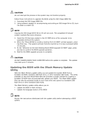
... to the Intel Desktop Board BIOS Upgrade CD-ROM" page, press any key to confirm the BIOS upgrade operation. 6. Wait for the BIOS upgrade process to complete.
CAUTION DO NOT POWER DOWN YOUR COMPUTER before the update is complete. The update may take up to 5 minutes.
Updating the BIOS with the Iflash Memory Update Utility
With the Iflash Memory update utility you can update the system BIOS from...
Product Guide - Page 57
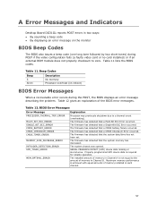
A Error Messages and Indicators
Desktop Board DG31GL reports POST errors in two ways: • By sounding a beep code • By displaying an error message on the monitor
BIOS Beep Codes
The BIOS also issues a beep code (one long tone followed by two short tones) during POST if the video configuration fails (a faulty video card or no card installed) or if an external ROM module...