Intel DG41TY - Desktop Board Classic Series Motherboard driver and firmware
Drivers and firmware downloads for this Intel item
Related Intel DG41TY Manual Pages
Download the free PDF manual for Intel DG41TY and other Intel manuals at ManualOwl.com
Product Guide - Page 2
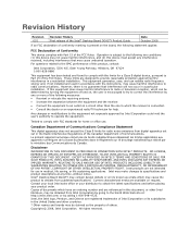
Revision History
Revision -001
Revision History First release of the Intel® Desktop Board DG41TY Product Guide
Date October 2008
If an FCC declaration of conformity marking is present on the board, the following statement applies:
FCC Declaration of Conformity
This device complies with Part 15 of the FCC Rules. Operation is subject to the following two conditions...
Product Guide - Page 3
...not be supported without further evaluation by Intel.
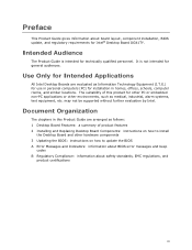
Document Organization
The chapters in this Product Guide are arranged as follows: 1 Desktop Board Features: a summary of product features 2 Installing and Replacing Desktop Board Components: instructions on how to install
the Desktop Board and other hardware components 3 Updating the BIOS: instructions on how to update the BIOS A Error Messages...
Product Guide - Page 5

... Systems 10 Desktop Board Components 11 Processor ...13 Main Memory...13 Intel® G41 Express Chipset 14
Intel® G41 Graphics Subsystem 15 Intel® GMA X4500 Graphics Controller (Intel® GMA X4500 15
Audio Subsystem 16 Legacy Input/Output (I/O) Controller 17 LAN Subsystem 17
RJ-45 LAN Connector LEDs 17 Hi-Speed USB 2.0 Support 18 Enhanced IDE Interface 18 Serial ATA...18...
Product Guide - Page 6
... the PCI Express x16 Card 41 Connecting the Diskette Drive Cable 42 Connecting the IDE Cable 43 Connecting the Serial ATA (SATA) Cables 44 Connecting to the Internal Headers and Connectors 45 S/PDIF Connector 46 Front Panel Audio Header 46 Serial Port Header 47 HD Audio Link Header 47 Chassis Intrusion Header 48 Front Panel Header 48 Alternate Front Panel Power LED Header 49 USB...
Product Guide - Page 7
... a Serial ATA Cable 44 21. Internal Headers and Connectors 45 22. Back Panel Audio Connectors 50 23. Location of the Chassis Fan Headers 51 24. Connecting Power Supply Cables 52 25. Location of the BIOS Configuration Jumper Block 53 26. Removing the Battery 59
Tables
1. Feature Summary 9 2. Intel Desktop Board DG41TY Components 12 3. Audio Jack Retasking Support 16 4. LAN Connector...
Product Guide - Page 10
Intel Desktop Board DG41TY Product Guide
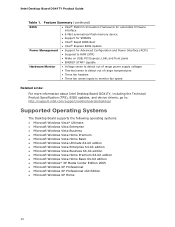
Table 1. Feature Summary (continued)
BIOS
• Intel® Platform Innovation Framework for extensible firmware interface
• 8 Mbit symmetrical flash memory device
• Support for SMBIOS
• Intel® Rapid BIOS Boot
• Intel® Express BIOS Update
Power Management • Support for Advanced Configuration and Power ...
Product Guide - Page 13
...
• Intel Desktop Board DG41TY http://www.intel.com/design/motherbd
http://support.intel.com/support/motherboards/desktop
• Supported processors
http://processormatch.intel.com
• Audio software and utilities http://www.intel.com/design/motherbd
• LAN software and drivers
http://www.intel.com/design/motherbd
Processor
CAUTION Failure to use an appropriate power supply...
Product Guide - Page 14
Intel Desktop Board DG41TY Product Guide
The Desktop Board supports the memory configurations listed below: • Four 240-pin Double Data Rate 2 (DDR2) SDRAM Dual Inline Memory Module
(DIMM) connectors with gold-plated contacts • Support for:
⎯ Non-ECC, 1.8 V, DDR2 800/667 MHz memory ⎯ Serial Presence Detect (SPD) memory only ⎯ Unbuffered, non-registered single- or ...
Product Guide - Page 15
Desktop Board Features
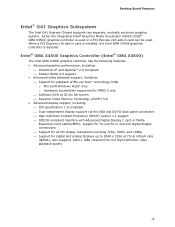
Intel® G41 Graphics Subsystem
The Intel G41 Express Chipset supports two separate, mutually exclusive graphics options. Either the integrated Intel® Graphics Media Accelerator X4500 (Intel® GMA X4500) graphics controller is used or a PCI Express x16 add-in card can be used. When a PCI Express x16 add-in card is installed, the Intel GMA X4500 graphics ...
Product Guide - Page 16
Intel Desktop Board DG41TY Product Guide
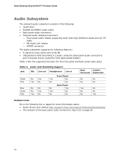
Audio Subsystem
The onboard audio subsystem consists of the following: • Intel® ICH7 • Realtek ALC888VC audio codec • Back panel audio connectors • Onboard audio headers/connectors:
⎯ Front panel audio header supporting both Intel High Definition Audio and AC '97 Audio
⎯ HD Audio Link header ⎯ S/PDIF ...
Product Guide - Page 17
... features: • CSMA/CD protocol engine • LAN connect interface between ICH7 and the LAN controller • PCI bus power management Related Links: Go to the following link for information about LAN software and drivers: http://support.intel.com/support/motherboards/desktop
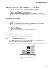
RJ-45 LAN Connector LEDs
Two LEDs are built into the RJ-45 LAN connector located on the back panel (see Figure...
Product Guide - Page 18
... and drivers that fully support USB 2.0 transfer rates. Disabling Hi-Speed USB in the BIOS reverts all USB 2.0 ports to USB 1.1 operation. This may be required to accommodate operating systems that do not support USB 2.0.
Enhanced IDE Interface
The board's IDE interface handles the exchange of information between the processor and peripheral devices such as hard disk drives and CD-ROM drives. The...
Product Guide - Page 19
...Two PCI bus connectors
BIOS
The BIOS provides the Power-On Self-Test (POST), the BIOS Setup program, the PCI/PCI Express and IDE auto-configuration utilities, and the video BIOS. The BIOS is stored in the Serial Peripheral Interface (SPI) Flash component. The BIOS can be updated by following the instructions on page 61 in Chapter 3.
Serial ATA and IDE Auto Configuration
If you install a Serial ATA...
Product Guide - Page 21
... technology (Suspend to RAM) ⎯ +5 V standby power indicator LED ⎯ Wake from USB ⎯ Power Management Event signal (PME#) wakeup support ⎯ WAKE# signal wake-up support • ENERGY STAR capable
ACPI
ACPI gives the operating system direct control over the power management and Plug and Play functions of a computer. The use of ACPI with the Desktop Board requires an operating...
Product Guide - Page 50
Intel Desktop Board DG41TY Product Guide
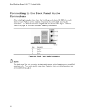
Connecting to the Back Panel Audio Connectors
After installing the audio driver from the Intel Express Installer CD-ROM, the multichannel audio feature can be enabled. Figure 22 shows the back panel audio connectors. The default connector assignments are shown in the figure. Refer to Table 3 on page 16 for audio connector retasking information.
Item ...
Product Guide - Page 53

...Table 15. Jumper Settings for the BIOS Setup Program Modes
Jumper Setting Mode Normal (default) (1-2)
Description
The BIOS uses the current configuration and passwords for booting.
Configure (2-3)
After the Power-On Self-Test (POST) runs, the BIOS displays the Maintenance Menu. Use this menu to clear passwords.
Recovery (None)
The BIOS recovers data in the event of a failed BIOS update.
53
Product Guide - Page 61
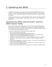
...; Flash Memory Update Utility and the ease of use of Windows-based installation wizards. To update the BIOS with the Intel Express BIOS Update utility: 1. Go to the Intel World Wide Web site:
http://support.intel.com/support/motherboards/desktop/ 2. Navigate to the Intel Desktop Board DG41TY page, click "[view] Latest BIOS
updates," and select the Express BIOS Update utility file. 3. Download the...
Product Guide - Page 62
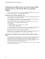
...• Intel Flash Memory Update Utility You can obtain either of these files through your computer supplier or by navigating to the Intel Desktop Board DG41TY page on the Intel World Wide Web site at: http://support.intel.com/support/motherboards/desktop Navigate to the Intel Desktop Board DG41TY page, click "[view] Latest BIOS updates," and select the ISO Image BIOS Update or Iflash BIOS Update...
Product Guide - Page 63
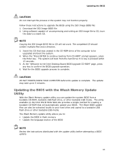
... to the Intel Desktop Board BIOS Upgrade CD-ROM" page, press any key to confirm the BIOS upgrade operation. 6. Wait for the BIOS upgrade process to complete.
CAUTION DO NOT POWER DOWN YOUR COMPUTER before the update is complete. The update may take up to 5 minutes.
Updating the BIOS with the Iflash Memory Update Utility
With the Iflash Memory update utility you can update the system BIOS from...
Product Guide - Page 65
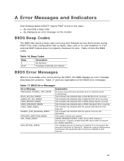
A Error Messages and Indicators
Intel Desktop Board DG41TY reports POST errors in two ways: • By sounding a beep code • By displaying an error message on the monitor
BIOS Beep Codes
The BIOS also issues a beep code (one long tone followed by two short tones) during POST if the video configuration fails (a faulty video card or no card installed) or if an external ROM module...