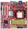
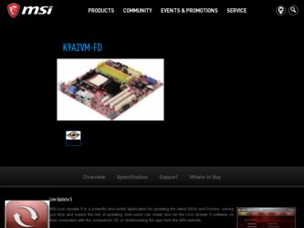
MSI K9A2VM-FD - SocketAM2+/125W CPU/AMD 780V/4DDR2-1066/Radeon driver and firmware
Drivers and firmware downloads for this MSI item
Related MSI K9A2VM-FD Manual Pages
Download the free PDF manual for MSI K9A2VM-FD and other MSI manuals at ManualOwl.com
User Guide - Page 2
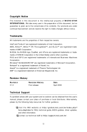
... obtained from the user's manual, please contact your place of purchase or local distributor. Alternatively, please try the following help resources for further guidance.
Visit the MSI website at http://global.msi.com.tw/index.php? func=faqIndex for FAQ, technical guide, BIOS updates, driver updates, and other information. Contact our technical staff at http://support.msi.com.tw/.
ii
User Guide - Page 4
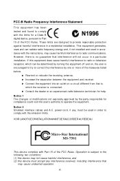
...digital device, pursuant to Part 15 of the FCC Rules. These limits are designed to provide reasonable protection against harmful interference in a residential installation. This equipment generates, uses and can radiate radio frequency energy and, if not installed and used in accordance with the instructions...experienced radio/television technician ...Shielded interface cables and A.C. power cord, if...
User Guide - Page 8

... CMOS Features 3-6 Advanced BIOS Features 3-9 Integrated Peripherals 3-12 Power Management Setup 3-14 H/W Monitor ...3-17 Cell Menu ...3-18 Load Fail-Safe / Optimized Defaults 3-22 BIOS Setting Password 3-23 Appendix A Realtek ALC888 Audio A-1 Installing the Realtek HD Audio Driver A-2 Software Configuration A-4 Hardware Setup A-19 Appendix B SATA RAID B-1 RAID Configuration B-2
viii
User Guide - Page 13
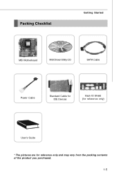
Packing Checklist
Getting Started
MSI Motherboard
MSI Driver/Utility CD
SATA Cable
Power Cable
Standard Cable for IDE Devices
Back IO Shield (for reference only)
User's Guide
* The pictures are for reference only and may vary from the packing contents of the product you purchased.
1-5
User Guide - Page 15
... chapter provides you with the information about hardware setup procedures. While doing the installation, be careful in holding the components and follow the installation procedures. For some components, if you install in the wrong orientation, the components will not work properly. Use a grounded wrist strap before handling computer components. Static electricity may damage the components...
User Guide - Page 17
Hardware Setup
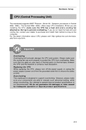
CPU (Central Processing Unit)
The mainboard supports AMD® Phenom / Athlon 64 / Sempron processors in Socket AM2 / AM2+. The Socket AM2 / AM2+ offers easy CPU installation. W hen you are installing the CPU, make sure the CPU has a heat sink and a cooling fan attached on the top to prevent overheating. If you do not have the heat sink and cooling...
User Guide - Page 18
.../ AM2+
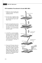
1. Please turn off the power and unplug the power cord before installing the CPU.
2. Pull the lever sideways away from the socket. Make sure that you raise the lever up to a 90degree angle.
Sliding the plate
Open the lever 90 degree
3. Look for the gold arrow on the CPU. The gold arrow should point...
User Guide - Page 19
Hardware Setup
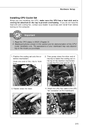
Installing CPU Cooler Set
W hen you are installing the CPU, make sure the CPU has a heat sink and a cooling fan attached on the top to prevent overheating. If you do not have the heat sink and cooling fan, contact your dealer to purchase and install them before turning on the computer.
Important
1. Read the CPU status in BIOS (Chapter 3). 2. Mainboard...
User Guide - Page 20
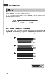
... Dual-Channel mode, the memory modules can transmit and receive data with two data bus lines simultaneously. Enabling Dual-Channel mode can enhance the system performance. Please refer to the following illustrations for population rules under Dual-Channel mode.
1
DIMM1
DIMM2
DIMM3
DIMM4
2
DIMM1
DIMM2
DIMM3
DIMM4
3
DIMM1
DIMM2
DIMM3
DIMM4
2-6
Installed Empty
User Guide - Page 21
Hardware Setup
Installing Memory Modules
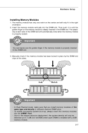
1. The memory module has only one notch on the center and will only fit in the right orientation.
2. Insert the memory module vertically into the DIMM slot. Then push it in until the golden finger on the memory module is deeply inserted in the DIMM slot. The plastic clip at each side...
User Guide - Page 22
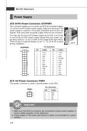
...power supply, please plug your power supply along with pin 1 & pin 13 (refer to the image at the right hand). There is also a foolproof design on pin 11, 12, 23 & 24 to avoid wrong installation...
+12V
23
+5V
12
+3.3V
24
GND
pin 13 pin 12
ATX 12V Power Connector: PWR1
This power connector is used to provide power to the CPU.
PWR1
3
4
1
2
Pin Definition
PIN
SIGNAL
1
GND
2
GND
3
...
User Guide - Page 25
Hardware Setup
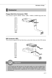
Connector
Floppy Disk Drive Connector: FDD1
This connector supports 360KB, 720KB, 1.2MB, 1.44MB or 2.88MB floppy disk drive.
FDD1
IDE Connector: IDE1
This connector supports IDE hard disk drives, optical disk drives and other IDE devices.
IDE1
Important
If you install two IDE devices on the same cable, you must configure the drives separately to master / slave mode by setting ...
User Guide - Page 46
...
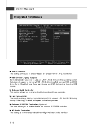
USB Controller This setting allows you to enable/disable the onboard USB 1.1/ 2.0 controller.
USB Device Legacy Support Set to [Enabled] if you need to use any USB 1.1/2.0 device in the operating system that does not support or have any USB 1.1/2.0 driver installed, such as DOS and SCO Unix. Set to [Disabled] only if you want to use any USB device other than the USB mouse.
Onboard LAN Controller...
User Guide - Page 54
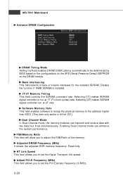
... function if 16MB SDRAM is installed.
1T/2T Memory Timing This field controls the SDRAM command rate. Selecting [1T] makes SDRAM signal controller to run at 1T (T=clock cycles) rate. Selecting [2T] makes SDRAM signal controller run at 2T rate.
Software Memory Hole This field enables software to remap the physical memory to the address higher than 00E0. (This item...
User Guide - Page 60
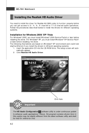
... environment and could look slightly different if you install the drivers in different operating systems.
1. Insert the application CD into the CD-ROM drive. The setup screen will automatically appear.
2. Click Realtek HD Audio Driver.
Important
Click here
The HD Audio Configuration software utility is under continuous update to enhance audio applications. Hence, the program screens shown here...
User Guide - Page 61
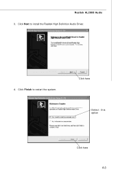
Realtek ALC888 Audio 3. Click Next to install the Realtek High Definition Audio Driver.
4. Click Finish to restart the system.
Click here
Select this option
Click here A-3
User Guide - Page 62
MS-7501 Mainboard
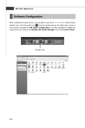
Software Configuration
After installing the audio driver, you are able to use the 2-, 4-, 6- or 8- channel audio feature now. Click the audio icon from the system tray at the lower-right corner of the screen to activate the HD Audio Configuration. It is also available to enable the audio driver by clicking the Realtek HD Audio M anager from the Control Panel.
Double click
A-4
User Guide - Page 80
...
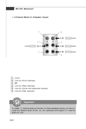
1
4
2
5
3 6
1 Line In 2 Line Out (Front channels) 3 MIC 4 Line Out (Rear channels) 5 Line Out (Center and Subwoofer channel) 6 Line Out (Side channels)
Important
To enable 7.1 channel audio-out function on Vista operating system, you have to install the Realtek Audio Driver. Or, the mainboard will support 5.1 channel audio-out only.
A-22
User Guide - Page 88
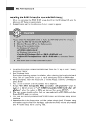
... a SATA RAID driver for yourself. 1. Insert the MSI CD into the CD-ROM drive. 2. Click the "Browse CD" on the Setup screen. 3. Copy all the contents in the : for Windows XP driver CD \ATI\ATIDrv\SBDrv\RAID for Windows Vista driver CD \ChipSet\ATI\Packages\Drivers\SBDrv\RAID\x86 and \ChipSet\ATI\Packages\Drivers\SBDrv\RAID\x64 to a formatted floppy disk. 4. The driver disk for RAID controller is...
User Guide - Page 89
SATA RAID
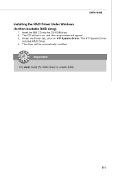
Installing the RAID Driver Under Windows (for Non-bootable RAID Array)
1. Insert the MSI CD into the CD-ROM drive. 2. The CD will auto-run and the setup screen will appear. 3. Under the Driver tab, click on ATI System Driver. The ATI System Driver
includes RAID Driver. 4. The driver will be automatically installed.
Important
You must install the RAID driver to enable RAID.
B-9