ASRock 4Core1600-DVI driver and firmware
Related ASRock 4Core1600-DVI Manual Pages
Download the free PDF manual for ASRock 4Core1600-DVI and other ASRock manuals at ManualOwl.com
User Manual - Page 3
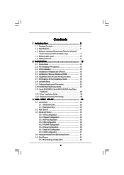
... of Heatsink and CPU fan 15 2.5 Installation of Memory Modules (DIMM 16 2.6 Expansion Slots (PCI and PCI Express Slots 18 2.7 DVI Graphics-SI Card Installation Guide 19 2.8 Jumpers Setup 21 2.9 Onboard Headers and Connectors 23 2.10 SATAII Hard Disk Setup Guide 27 2.11 Serial ATA (SATA) / Serial ATAII (SATAII) Hard Disks
Installation 28 2.12 Driver Installation Guide 28 2.13 Untied...
User Manual - Page 4
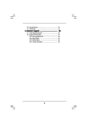
3.6 Security Screen 43 3.7 Exit Screen 44
4 Software Support 45
4.1 Install Operating System 45 4.2 Support CD Information 45
4.2.1 Running Support CD 45 4.2.2 Drivers Menu 45 4.2.3 Utilities Menu 45 4.2.4 Contact Information 45
4
User Manual - Page 5
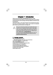
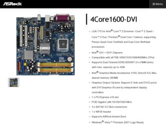
...-DVI Motherboard (Micro ATX Form Factor: 9.6-in x 9.6-in, 24.4 cm x 24.4 cm)
ASRock 4Core1600-DVI Quick Installation Guide ASRock 4Core1600-DVI Support CD One 80-conductor Ultra ATA 66/100 IDE Ribbon Cable One Ribbon Cable for a 3.5-in Floppy Drive One Serial ATA (SATA) Data Cable (Optional) One Serial ATA (SATA) HDD Power Cable (Optional) One ASRock 6CH I/O Panel Shield One DVI Graphics-SI Card...
User Manual - Page 7
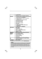
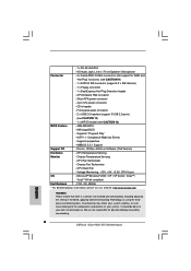
... support for RAID and
"Hot Plug" functions) (see CAUTION 11)
- 1 x ATA100 IDE connector (supports 2 x IDE devices)
- 1 x Floppy connector
- 1 x DeskExpress Hot Plug Detection header
- CPU/Chassis FAN connector
- 24 pin ATX power connector
- 4 pin 12V power connector
- CD in header
- Front panel audio connector
- 2 x USB 2.0 headers (support 3 USB 2.0 ports)
(see CAUTION 12)
- 1 x WiFi...
User Manual - Page 8
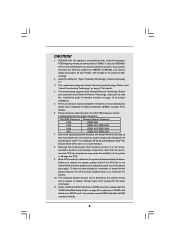
... shared memory size is defined by the chipset vendor
and is subject to change. Please check Intel® website for the latest
information.
11. Before installing SATAII hard disk to SATAII connector, please read the
"SATAII Hard Disk Setup Guide" on page 26 to adjust your SATAII hard
disk drive to SATAII mode. You can also connect SATA hard disk to...
User Manual - Page 9
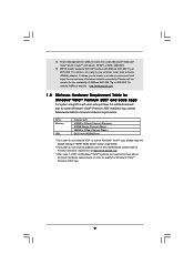
.... Power Management for USB 2.0 works fine under Microsoft® Windows® VistaTM 64-bit / VistaTM / XP 64-bit / XP SP1 or SP2 / 2000 SP4.
13. WiFi/E header supports WiFi+AP function with ASRock WiFi-802.11g or WiFi-802.11n module, an easy-to-use wireless local area network (WLAN) adapter. It allows you to create a wireless environment and enjoy the convenience of wireless network...
User Manual - Page 11
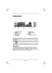
...) 6 Line Out (Lime)
7 Microphone (Pink) 8 USB 2.0 Ports (USB01) 9 VGA Port 10 COM Port 11 PS/2 Keyboard Port (Purple)
* To enable Multi-Streaming function, you need to connect a front panel audio cable to the front
panel audio header. Please refer to below steps for the software setting of Multi-Streaming.
For Windows® XP:
After restarting your computer, you will find "Mixer" tool on...
User Manual - Page 20
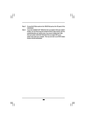
... port on the I/O panel of this motherboard. If you have installed Intel® VGA driver from our support CD to your system already, you can freely enjoy the benefits of DVI-D output function with this motherboard after your system boots. If you haven't installed Intel® VGA driver yet, please install Intel® VGA driver from our support CD to your system and restart your computer...
User Manual - Page 24
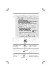
... don't
need to connect them for AC'97 audio panel.
E. Enter BIOS Setup Utility. Enter Advanced Settings, and then select
Chipset Configuration. Set the Front Panel Control option from
[Auto] to [Enabled].
F. Enter Windows system. Click the icon on the lower right hand
taskbar to enter Realtek HD Audio Manager.
For Windows® 2000 / XP / XP 64-bit OS:
Click...
User Manual - Page 26
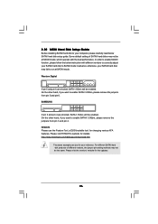
... Hard Disk Setup Guide
Before installing SATAII hard disk to your computer, please carefully read below SATAII hard disk setup guide. Some default setting of SATAII hard disks may not be at SATAII mode, which operate with the best performance. In order to enable SATAII function, please follow the below instruction with different vendors to correctly adjust your SATAII hard disk to SATAII...
User Manual - Page 27
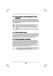
... bridge chipset that supports Serial ATA (SATA) / Serial ATAII (SATAII) hard disks. You may install SATA / SATAII hard disks on this motherboard for internal storage devices. This section will guide you to install the SATA / SATAII hard disks.
STEP 1: Install the SATA / SATAII hard disks into the drive bays of your chassis. STEP 2: Connect the SATA power cable to the SATA / SATAII hard disk. STEP...
User Manual - Page 28
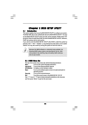
... the system time/date information
Advanced To set up the advanced BIOS features
H/W Monitor To display current hardware status
Boot
To set up the default system device to locate and load the
Operating System
Security
To set up the security features
Exit
To exit the current screen or the BIOS SETUP UTILITY
Use < > key or < > key to choose among...
User Manual - Page 31
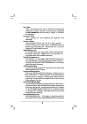
... Value This is a read-only item, which displays the ratio actual value of this motherboard.
Enhance Halt State All processors support the Halt State (C1). The C1 state is supported through the native processor instructions HLT and MWAIT and requires no hardware support from the chipset. In the C1 power state, the processor maintains the context of the system caches.
Max...
User Manual - Page 32
...will be hidden if the current CPU does not support Intel (R) SpeedStep(tm) tech..
Please note that enabling this function may reduce CPU voltage and lead to system stability or compatibility issue with some power supplies. Please set this item to [Disable] if above issue occurs.
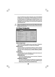
3.3.2 Chipset Configuration
BIOS SETUP UTILITY Advanced
Chipset Configuration
Memory Remap Feature
[Disabled]
DRAM...
User Manual - Page 33
... Clocks].
Primary Graphics Adapter This allows you to select [Onboard], [PCI] or [PCI Express] as the boot graphic adapter priority. The default value is [PCI].
Internal Graphics Mode Select If you select [Auto], the onboard VGA will be automatically disabled when you install VGA card; the onboard VGA will be enabled without the installation of any add-on VGA card. If you select...
User Manual - Page 45
...-ROM drive. The CD automatically displays the Main Menu if "AUTORUN" is enabled in your computer. If the Main Menu did not appear automatically, locate and double click on the file "ASSETUP.EXE" from the BIN folder in the Support CD to display the menus. 4.2.2 Drivers Menu The Drivers Menu shows the available devices drivers if the system detects installed devices. Please install...
Quick Installation Guide - Page 4
...in x 9.6-in, 24.4 cm x 24.4 cm)
ASRock 4Core1600-DVI Quick Installation Guide ASRock 4Core1600-DVI Support CD One 80-conductor Ultra ATA 66/100 IDE Ribbon Cable One Ribbon Cable for a 3.5-in Floppy Drive One Serial ATA (SATA) Data Cable (Optional) One Serial ATA (SATA) HDD Power Cable (Optional) One ASRock 6CH I/O Panel Shield One DVI Graphics-SI Card
4 ASRock 4Core1600-DVI Motherboard
English
Quick Installation Guide - Page 6
... support for RAID and
"Hot Plug" functions) (see CAUTION 11)
- 1 x ATA100 IDE connector (supports 2 x IDE devices)
- 1 x Floppy connector
- 1 x DeskExpress Hot Plug Detection header
- CPU/Chassis FAN connector
- 24 pin ATX power connector
- 4 pin 12V power connector
- CD in header
- Front panel audio connector
- 2 x USB 2.0 headers (support 3 USB 2.0 ports)
(see CAUTION 12)
- 1 x WiFi...
Quick Installation Guide - Page 22
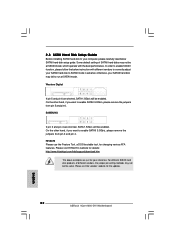
..., for changing various ATA features. Please visit HITACHI's website for details: http://www.hitachigst.com/hdd/support/download.htm
The above examples are just for your reference. For different SATAII hard disk products of different vendors, the jumper pin setting methods may not be the same. Please visit the vendors' website for the updates.
22 ASRock 4Core1600-DVI Motherboard
English
Quick Installation Guide - Page 24
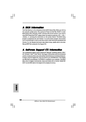
... using the Support CD, insert the CD into your CD-ROM drive. It will display the Main Menu automatically if "AUTORUN" is enabled in your computer. If the Main Menu does not appear automatically, locate and double-click on the file "ASSETUP. EXE" from the BIN folder in the Support CD to display the menus.
24 ASRock 4Core1600-DVI Motherboard
English