ASRock 775i915PL-M driver and firmware
Related ASRock 775i915PL-M Manual Pages
Download the free PDF manual for ASRock 775i915PL-M and other ASRock manuals at ManualOwl.com
User Manual - Page 3
... 13 2.5 Installation of Memory Modules (DIMM 14 2.6 Expansion Slots 15 2.7 Surround Display Feature 16 2.8 Jumpers Setup 16 2.9 Onboard Headers and Connectors 17 2.10 Serial ATA (SATA) Hard Disks Installation 20
3 BIOS SETUP UTILITY 21
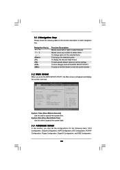
3.1 Introduction 23 3.1.1 BIOS Menu Bar 23 3.1.2 Navigation Keys 22
3.2 Main Screen 22 3.3 Advanced Screen 22
3.3.1 CPU Configuration 23 3.3.2 Chipset...
User Manual - Page 4
4 Software Support 36
4.1 Install Operating System 36 4.2 Support CD Information 36
4.2.1 Running Support CD 36 4.2.2 Drivers Menu 36 4.2.3 Utilities Menu 36 4.2.4 "LGA 775 CPU Installation Live Demo" Program .. 36 4.2.5 Contact Information 36
4
User Manual - Page 5
...
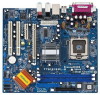
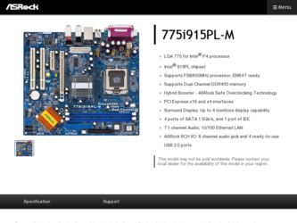
ASRock 775i915PL-M Motherboard (Micro ATX Form Factor: 9.6-in x 8.6-in, 24.4 cm x 21.8 cm)
ASRock 775i915PL-M Quick Installation Guide ASRock 775i915PL-M Support CD
(including LGA 775 CPU Installation Live Demo) One 80-conductor Ultra ATA 66/100 IDE Ribbon Cable One Ribbon Cable for a 3.5-in Floppy Drive One Serial ATA (SATA) Data Cable One Serial ATA (SATA) HDD Power Cable (Optional) One ASRock...
User Manual - Page 7
... than the recommended CPU bus frequencies may cause the instability of the system or damage the CPU. 7. Because of Intel 915PL chipset limitation, Windows 98 / ME does not support USB 2.0 but only USB 1.1. Besides, after installing Windows 98 / ME, two display adapter controllers will appear in "Display Adapters" of "Device Manager". Please remove one of the display adapter controllers, and then...
User Manual - Page 10
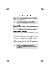
Chapter 2 Installation
775i915PL-M is a Micro ATX form factor (9.6" x 8.6", 24.4 x 21.8 cm) motherboard. Before you install the motherboard, study the configuration of your chassis to ensure that the motherboard fits into it.
Make sure to unplug the power cord before installing or removing the motherboard. Failure to do so may cause physical injuries to you and damages to motherboard components.
...
User Manual - Page 11
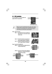
... on the hook to clear retention tab.
Step 1-2. Rotate the load lever to fully open position at approximately 135 degrees.
Step 1-3. Rotate the load plate to fully open position at approximately 100 degrees.
Step 2. Insert the 775-LAND CPU: Step 2-1. Hold the CPU by the edges where are marked with black lines.
Step 2-2. Orient...
User Manual - Page 13
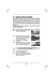
... kindly refer to the instruction manuals of your CPU fan and heatsink.
Below is an example to illustrate the installation of the heatsink for 775-LAND CPU. Step 1. Apply thermal interface material onto center
of IHS on the socket surface.
Step 2.
Step 3. Step 4.
Place the heatsink onto the socket. Ensure fan cables are oriented on side...
User Manual - Page 14
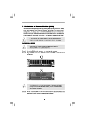
2.5 Installation of Memory Modules (DIMM)
775i915PL-M motherboard provides two 184-pin DDR (Double Data Rate) DIMM slots, and supports Dual Channel Memory Technology. For dual channel configuration, you always need to install two identical (the same brand, speed, size and chip-type) memory modules in the DDR DIMM slots to activate Dual Channel Memory Technology. Otherwise, it will operate at...
User Manual - Page 15
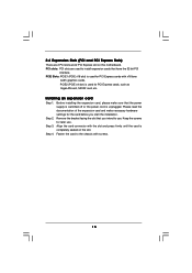
... for PCI Express cards with x16 lane
width graphics cards. PCIE2 (PCIE x4 slot) is used for PCI Express cards, such as GigaLAN card, SATA2 card, etc.
Installing an expansion card
Step 1. Before installing the expansion card, please make sure that the power supply is switched off or the power cord is unplugged. Please read the documentation of the expansion card and make necessary hardware settings...
User Manual - Page 16
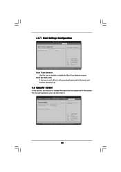
2.7 Surround Display Feature
This motherboard supports Surround Display upgrade. With the external add-on PCI Express VGA card, you can easily enjoy the benefits of Surround Display feature. For the detailed instruction, please refer to the document at the following path in the Support CD: ..\ Surround Display
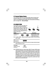
2.8 Jumpers Setup
The illustration shows how jumpers are
setup. When the jumper cap ...
User Manual - Page 20
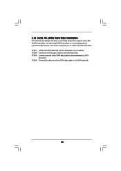
...10 Serial ATA (SATA) Hard Disks Installation
This motherboard adopts Intel ICH6 south bridge chipset that supports Serial ATA (SATA) hard disks. You may install SATA hard disks on this motherboard for internal storage devices. This section will guide you to install the SATA hard disks. STEP 1: Install the SATA hard disks into the drive bays of your chassis. STEP 2: Connect the SATA power cable to...
User Manual - Page 21

... the system time/date information
Advanced To set up the advanced BIOS features
H/W Monitor To display current hardware status
Boot
To set up the default system device to locate and load the
Operating System
Security
To set up the security features
Exit
To exit the current screen or the BIOS SETUP UTILITY
Use < > key or < > key to choose among...
User Manual - Page 22
...the BIOS SETUP UTILITY, the Main screen will appear and display the system overview
BIOS SETUP UTILITY
Main Advanced
H/W Monitor
Boot
Security
Exit
System Overview
System Time System Date
[14:00:09] [Thu 05/05/2005]
BIOS Version
: 775i915PL-M BIOS P1.00
Processor Type : Intel (R) CPU 3.60 GHz
Processor Speed : 3600 MHz
Microcode Update : F43/04
Cache Size
: 2048KB
Total Memory
DIMM...
User Manual - Page 24
... installed processor.
Ratio Actual Value This is a read-only item, which displays the ratio actual value of this motherboard.
CPU Thermal Throttling You may select [Enabled] to enable P4 CPU internal thermal control mechanism to keep the CPU from overheated.
Hyper Threading Technology To enable this feature, it requires a computer system with an Intel Pentium®4 processor that supports Hyper...
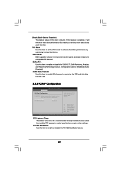
User Manual - Page 27
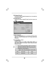
...[SATA 1, SATA 2, SATA 3, SATA 4], and [IDE 1, SATA 2, SATA 4]. If it is set to [IDE 1, SATA 2, SATA 4], then SATA1, SATA3 will not work.
Because Intel® ICH6 south bridge only supports four IDE devices under legacy OS (Windows ME / 98SE / NT), you have to choose [SATA 1, SATA 2, SATA 3, SATA 4], or [IDE 1, SATA 2, SATA 4] when the installed device is used with legacy OS.
[SATA 1, SATA 2, SATA...
User Manual - Page 28
... the example in the following instruction.
BIOS SETUP UTILITY Advanced
Primary IDE Master
Device Vendor Size LBA Mode Block Mode PIO Mode Async DMA Ultra DMA S.M.A.R.T.
Type LBA/Large Mode Block (Multi-Sector Transfer) PIO Mode DMA Mode S.M.A.R.T. 32Bit Data Transfer
:Hard Disk :ST340014A :40.0 GB :Supported :16Sectors :4 :MultiWord DMA-2 :Ultra DMA-5 :Supported
[Auto] [Auto] [Auto] [Auto...
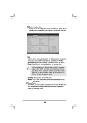
User Manual - Page 29
... transfer rate.
3.3.5 PCIPnP Configuration
BIOS SETUP UTILITY Advanced
PCI / PnP Configuration
WARNING: Setting wrong values in below actions may cause system to malfunction.
PCI Latency Timer PCI IDE BusMaster
[32] [Enabled]
Value in units of PCI clocks for PCI device latency timer register.
+F1 F9 F10 ESC
Select Screen Select Item Change Option General Help Load Defaults Save and Exit...
User Manual - Page 34
... for the system. For the user password, you may also clear it.
BIOS SETUP UTILITY
Main
Advanced
H/W Monitor
Boot
Security
Exit
Security Settings
Supervisor Password : Not Installed
User Password
: Not Installed
Change Supervisor Password Change User Password
Install or Change the password.
Select Screen Select Item Enter Change F1 General Help F9 Load Defaults F10 Save and Exit ESC...
User Manual - Page 36
... CD to display the menus.
4.2.2 Drivers Menu The Drivers Menu shows the available devices drivers if the system detects installed devices. Please install the necessary drivers to activate the devices.
4.2.3 Utilities Menu The Utilities Menu shows the applications software that the motherboard supports. Click on a specific item then follow the installation wizard to install it.
4.2.4 "LGA 775 CPU...