Asus AP1720-E1 driver and firmware

Related Asus AP1720-E1 Manual Pages
Download the free PDF manual for Asus AP1720-E1 and other Asus manuals at ManualOwl.com
User Guide - Page 2
... or liability for any errors or inaccuracies that may appear in this manual, including the products and software described in it. Product warranty or service will not be extended if: (1) the product is repaired, modified or altered, unless such repair, modification of alteration is authorized in writing by ASUS; or (2) the serial number of the product...
User Guide - Page 3
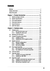
... Installing a CPU 2-6 2.3.2 Installing the CPU heatsink and fan 2-7 2.4 System memory 2-10 2.4.1 Memory configurations 2-10 2.4.2 Installing a DIMM 2-11 2.4.3 Removing a DIMM 2-11 2.5 Front panel assembly 2-12 2.5.1 Removing the front panel assembly 2-12 2.5.2 Re-installing the front panel assembly 2-14 2.6 5.25-inch drives 2-15 2.7 Hard disk drives 2-18 2.7.1 Installing a hot-swap SCSI...
User Guide - Page 4
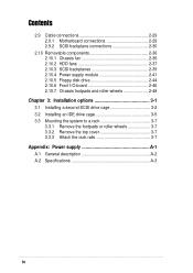
... Cable connections 2-29 2.9.1 Motherboard connections 2-29 2.9.2 SCSI backplane connections 2-30
2.10 Removable components 2-36 2.10.1 Chassis fan 2-36 2.10.2 HDD fans 2-37 2.10.3 SCSI backplanes 2-39 2.10.4 Power supply module 2-41 2.10.5 Floppy disk drive 2-44 2.10.6 Front I/O board 2-46 2.10.7 Chassis footpads and roller wheels 2-48
Chapter 3: Installation options 3-1
3.1 Installing...
User Guide - Page 5
... for a Class B digital device, pursuant to Part 15 of the FCC Rules. These limits are designed to provide reasonable protection against harmful interference in a residential installation. This equipment generates, ...the dealer or an experienced radio/TV technician for help.
WARNING! The use of shielded cables for connection of the monitor to the graphics card is required to assure compliance with...
User Guide - Page 6
...'s safety. Use the power cable with a properly grounded electrical outlet to avoid electrical shock.
Lithium-Ion Battery Warning
CAUTION! Danger of explosion if battery is incorrectly replaced. Replace only with the same or equivalent type recommended by the manufacturer. Dispose of used batteries according to the manufacturer's instructions.
CD-ROM Drive Safety Warning
CLASS 1 LASER...
User Guide - Page 7
... the general features of the AP1720-E1 server. It includes sections on front panel and rear panel specifications. 2. Chapter 2: Hardware setup This chapter lists the hardware setup procedures that you have to perform when installing or removing system components. 3. Chapter 3: Configuration options This chapter describes how to install optional components and devices into the barebone server and...
User Guide - Page 8
References
Refer to the following sources for additional information, and for product and software updates. 1. ASUS PC-DL Deluxe motherboard user guide
This manual contains detailed information about the PC-DL Deluxe motherboard. 2. ASUS websites The ASUS websites worldwide provide updated information for all ASUS hardware and software products. Refer to the ASUS contact information.
viii
User Guide - Page 10
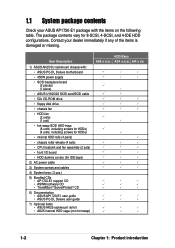
... roller wheels (4 sets)
• CPU heatsink and fan assembly (2 sets)
• front I/O board
• HDD dummy covers (for IDE bays)
2) AC power cable
3) System screws and cables
4) System keys ( 2 pcs.)
5) Bundled CDs • AP1720-E1 support CD • ASWM software CD • TrendMicro® ServerProtect® CD
6) Documentation • ASUS AP1720-E1 user guide • ASUS PC-DL Deluxe...
User Guide - Page 12
...
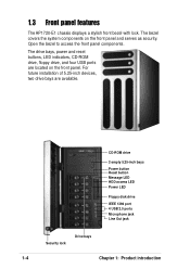
The AP1720-E1 chassis displays a stylish front bezel with lock. The bezel covers the system components on the front panel and serves as security. Open the bezel to access the front panel components.
The drive bays, power and reset buttons, LED indicators, CD-ROM drive, floppy drive, and four USB ports are located on the front panel. For future installation of...
User Guide - Page 14
...9
7
5
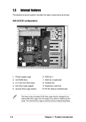
1. Power supply cage 2. CD-ROM drive 3. 2 x 5.25-inch drive bays 4. first drive cage (upper) 5. second drive cage (lower)
6. HDD fan 1 7. HDD fan 2 (optional) 8. Chassis fan 9. Expansion card lock 10. PC-DL Deluxe motherboard
The lower 4-bay hot swap SCSI drive cage may be changed to an internal IDE drive cage (non-hot swap) if you wish to install long PCI cards. The internal drive cage...
User Guide - Page 16
...
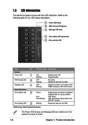
Message LED
!
Hard disk drives Drive Status LED
Drive Activity LED
Display status Description
ON Blinking
OFF Blinking
OFF Blinking
System power ON Suspend mode
No activity Read/write data into the HDD
System is normal; no incoming event ASMS indicates a HW monitor event
Green Red Red-Blinking
Blinking
Bridge board connected to backplane Installed HDD is in...
User Guide - Page 17
Chapter 2
This chapter lists the hardware setup procedures that you have to perform when installing or removing system components.
Hardware setup
ASUS AP1720-E1 barebone server
2-1
User Guide - Page 19
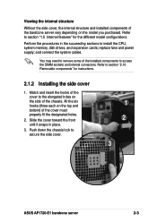
...CPU, system memory, disk drives, and expansion cards; replace fans and power supply; and connect the system cables.
You may need to remove some of the installed components to access the DIMM sockets and internal connectors. Refer to section "2.10 Removable components" for instructions.
2.1.2 Installing...Push down the chassis lock to secure the side cover.
1 2
3
ASUS AP1720-E1 barebone server
2-3
User Guide - Page 20
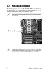
... the ASUS PC-DL Deluxe motherboard already installed. The motherboard is secured to the chassis by nine (9) screws as indicated by circles in the illustration below.
Refer to the motherboard user guide for detailed information on the motherboard.
This side towards the rear of the chassis
Make sure to unplug the power cord before installing or removing any motherboard component...
User Guide - Page 21
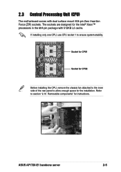
... package with 512KB L2 cache.
If installing only one CPU, use CPU socket 1 to ensure system stability.
Socket for CPU1
Socket for CPU2
Before installing the CPU, remove the chassis fan attached to the inner side of the rear panel to allow enough space for the installation. Refer to section "2.10 Removable components" for instructions.
ASUS AP1720-E1 barebone server
2-5
User Guide - Page 22
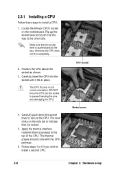
2.3.1 Installing a CPU
Follow these steps to install a CPU.
1. Locate the 604-pin CPU1 socket on the motherboard. Flip up the socket lever and push it all the way to the other side.
Make sure that the socket lever is pushed back all the way, otherwise the CPU does not fit in completely.
2. Position the CPU above the socket...
User Guide - Page 23
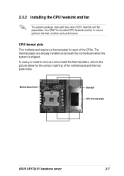
... motherboard requires a thermal plate for each of the CPUs. The thermal plates are already installed underneath the motherboard when the system is shipped. In case you need to remove and re-install the thermal plates, refer to the picture below for the correct matching of the motherboard and thermal plate holes.
Motherboard hole
Standoff CPU thermal plate
ASUS AP1720-E1...
User Guide - Page 24
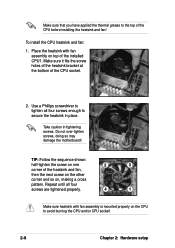
...installed CPU1. Make sure it fits the screw holes of the heatsink bracket at the bottom of the CPU socket.
2. Use a Phillips screwdriver to tighten all four screws enough to secure the heatsink in place.
Take caution in tightening screws. Do not over-tighten screws, doing so may damage the motherboard... properly on the CPU to avoid burning the CPU and/or CPU socket!
2-8
Chapter 2: Hardware setup
User Guide - Page 68
... barebone system package. These items are purchased separately.
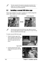
3.1 Installing a second SCSI drive cage
Perform this installation if you wish to upgrade your 4-SCSI configuration system (AS4 model) to an 8-SCSI configuration.
4-SCSI configuration
8-SCSI configuration
Clear the space under the first SCSI drive cage. Make sure that the pre-connected cables are properly routed so they do not get...
User Guide - Page 71
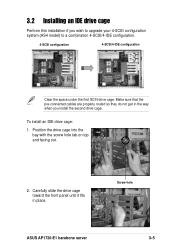
... so they do not get in the way when you install the second drive cage.
To install an IDE drive cage:
1. Position the drive cage into the bay with the screw hole tab on top and facing out.
2. Carefully slide the drive cage toward the front panel until it fits in place.
Screw hole
ASUS AP1720-E1 barebone server
3-5