Biostar TFORCE4 U driver and firmware

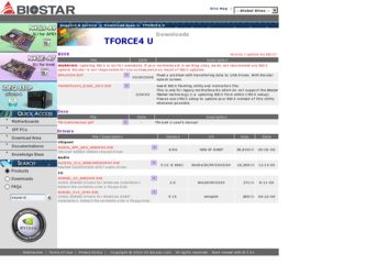
Related Biostar TFORCE4 U Manual Pages
Download the free PDF manual for Biostar TFORCE4 U and other Biostar manuals at ManualOwl.com
TForce4 U user's manual - Page 1
... be responsible for any mistakes found in this user's manual. All the brand and product names are trademarks of their respective companies.
PACKAGE CHECKLIST
FDD Cable x 1 HDD Cable x 1 User's Manual x 1 Overclock Guide x 1 Serial ATA Cable x 2 Fully Setup Driver CD x 1 Rear I/O Panel for ATX Case x 1 SPDIF Cable x 1 (optional) USB 2.0 Cable x 1 (optional) IEEE 1394A Cable x 1 (optional)
i
User...
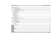
TForce4 U user's manual - Page 2
...
B. Memory Space...4
C. DDR Installation Notice...4
D. Know your CPU version ...4
2.3
PERIPHERALS ...5
A. Card and I/O Slots:...5
B. Connectors and Headers:...6
CHAPTER 3: NVIDIA RAID FUNCTIONS ...11
3.1
OPERATION SYSTEM ...11
3.2 RAID ARRAYS ...11
3.3
HOW RAID WORKS ...12
CHAPTER 4: USEFUL HELP...14
4.1
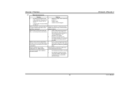
AWARD BIOS BEEP CODE...14
4.2
EXTRA INFORMATION ...14
A. BIOS Update...14...
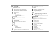
TForce4 U user's manual - Page 3
...
2 on-board connectors support 4 IDE disk drives.
Supports PIO mode 0~4, Block Mode and Ultra DMA 33/66/100/133 bus master mode.
1
TForce4/ TForce4 U
AC'97 Audio Sound Codec
Chip: ALC850, supports 8 channels audio output.
IEEE 1394A Chip
Chip: VIA VT6307, supports 2 ports with transfer up to 400Mb/s.
Gigabit Ethernet LAN
NVIDIA Gigabit MAC + VITESSE Gigabit PHY VSC8201.
Supports ACPI power...
TForce4 U user's manual - Page 5
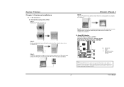
... cable into the JCFAN1. This completes the installation.
B. About FAN Headers CPU FAN Power Header: JCFAN1 System Fan Power Headers: JSFAN1/JSFAN2 North Bridge Fan Power Header: JNBFAN1
JCFAN1
31
JNBFAN1 1 3
JSFAN2 1 3
Codec
BIOS
JSFAN1
31
Pin Assignment
1 Ground 2 +12V 3 FAN RPM rate sense
(Does not support JSFAN2.)
Note:
JCFAN1and JNBFAN1 reserve system cooling fan with Smart Fan Control...
TForce4 U user's manual - Page 6
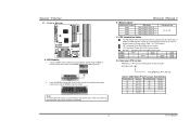
Biostar T-Series 2.2 SYSTEM MEMORY
DIMM3 DIMM1 DIMM4 DIMM2
Codec
BIOS...the modules out vertically.
TForce4/ TForce4 U
B. Memory Space
DIMM Socket Location DIMM1...memory module.
Star sign "*" represents leave the DIMM socket empty.
DIMM1 DIMM2 DIMM3 DIMM4
SS/DS * * *
* * SS/DS *
SS/DS SS/DS
* *
* * SS/DS SS/DS
SS/DS SS/DS SS/DS SS/DS
D. Know your CPU version
AMD Athlon™ 64 Processor...
TForce4 U user's manual - Page 8
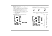
... restarts, the system will automatically set the AGP VGA card as the graphics adapter. 2. Re-install your operating system to ensure the AGP VGA card function can be used.
Note: Please go to "http://www.biostar.com.tw" for more detailed information about XGP compatible AGP cards.
XGP1
Codec
BIOS
TForce4/ TForce4 U
B. Connectors and Headers:
How to setup Jumpers
The illustration shows how...
TForce4 U user's manual - Page 13
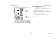
... voltage can be manually adjusted under CMOS setup.
2. When "JDDR_OV>3V" jumper cap is placed on Pin 1-2, memory voltage will be fixed at 3.3V automatically, and can't be adjusted under COMS setup.
3. Before setting memory voltage overclocking, please ensure that your DDR supports up to 3V. (Consulting your DDR supplier)
TForce4/ TForce4 U
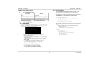
Chapter 3: NVIDIA RAID Functions
3.1
OPERATION SYSTEM...
TForce4 U user's manual - Page 15
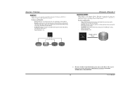
... the drives.
- Drawbacks: Decreases performance because of the difficulty in using drives concurrently.
- Fault Tolerance: Yes.
Single Logical Drive
Disk 1: 40GB Disk 2: 80GB Disk 3: 40GB Disk 4: 120GB
※ For more detailed setup information, please refer to the Driver CD, or go to http://www.nvidia.com/page/pg_20011106217193.html to download NVIDIA nForce Tutorial Flash.
13
User's Manual
TForce4 U user's manual - Page 16
... download the respective BIOS from
Biostar website. 4. Copy "AWDFLASH.exe" and respective BIOS onto floppy disk. 5. Insert the bootable disk into floppy drive and press Enter. 6. System will boot-up to DOS prompt. 7. Type "Awdflash xxxx.bf/sn/py/r" in DOS prompt. 8. System will update BIOS automatically and restart. 9. The BIOS has been recovered and will work properly.
TForce4/ TForce4 U
B. CPU...
TForce4 U user's manual - Page 17
... the
on, power indicator lights are lit, and DIMM, press down firmly until the module
hard drive is spinning.
snaps into place.
System does not boot from hard disk 1. drive, can be booted from optical drive.
2.
Check cable running from disk to disk controller board. Make sure both ends are securely plugged in; check the drive type in the standard CMOS setup.
Backing...