Dell FC4500 driver and firmware

Related Dell FC4500 Manual Pages
Download the free PDF manual for Dell FC4500 and other Dell manuals at ManualOwl.com
Reference Guide - Page 6
... 3
Servicing and Upgrading a DPE
Monitoring DPE Status 3-1 Handling CRUs 3-4
Power Issues and CRUs 3-4 Avoiding Electrostatic Discharge (ESD) Damage 3-6 Precautions When Removing, Installing, or Storing CRUs ........3-7 Precautions When Handling Optical Cables 3-8 Replacing or Adding a Disk Module 3-9 Replacing the SP Fan Pack 3-14 Replacing an Optical GBIC 3-17
Installing an Optical GBIC...
Reference Guide - Page 11
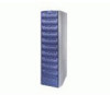
... manual describes how to install the EMC Fibre Channel Disk-Array Processor Enclosure (DPE) Rackmount Model FC4500, and how to replace and add customer-replaceable units (CRUs).
If you will install and service the rackmount DPE, you should read this manual. After reading it, you will be able to install a rackmount DPE, replace any CRUs that may fail, and upgrade...
Reference Guide - Page 12
...the warning.
EMC uses the following type style conventions in this guide:
Boldface
Specific filenames or complete paths. Window names and menu items in text. Emphasis in cautions and warnings...type, displayed text, or program listings. For example:
Fixed italic
QUERY [CUU=cuu|VOLSER=volser]
Arguments used in examples of command line syntax.
xii
EMC Fibre Channel Disk-Array Processor Enclosure...
Reference Guide - Page 25
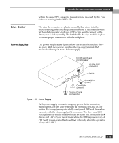
... and shares load currents with the other supply, if it is present. The drive and LCC voltage lines have individual soft-start switches that protect the disk drives and LCCs if you install them while the DPE is powered up. A CRU with power-related faults will not adversely affect the operation of any other CRU.
Link Control Cards (LCCs...
Reference Guide - Page 49
... Storing CRUs .........3-7 • Precautions When Handling Optical Cables 3-8 • Replacing or Adding a Disk Module 3-9 • Replacing the SP Fan Pack 3-14 • Replacing an Optical GBIC 3-17 • Removing an SP or an SP Filler Module 3-21 • Installing or Replacing an SP Memory Module 3-24 • Installing an SP or SP Filler Module 3-26 • Replacing...
Reference Guide - Page 51
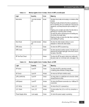
... DPE Active DPE Check SP Fan Pack Check
Quantity
Color
1 per disk module Green slot
1 per disk module Amber slot
1
Green
1
Amber
1
Amber
Meaning
Off when the module slot is empty or contains a filler module. Flashing (mostly off) when the drive is powered up but not spinning; this is a normal part of the spin-up...
Reference Guide - Page 52
Servicing and Upgrading a DPE
3
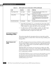
Table 3-2 Status Lights Color Codes, Back of DPE (continued)
Light Power Supply Check
Cooling Check
Quantity 1 per supply
1 per supply
Drive Fan Pack Check 1 on fan pack
Color Amber Amber
Yellow
Meaning
On when the power supply is faulty or is not receiving ac line voltage.
Flashing when multiple fans in the drive fan...
Reference Guide - Page 54
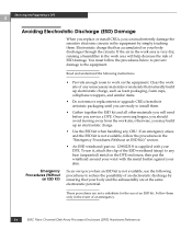
...to prevent damage to the equipment.
Read and understand the following instructions.
Emergency Procedures (Without
an ESD Kit)
• Provide ...upgrade CRUs from their antistatic packaging until you are ready to install them.
• Gather together the ESD kit and all other materials you will need before you service a DPE. Once servicing...Disk-Array Processor Enclosure (DPE) Hardware Reference
Reference Guide - Page 55
Servicing and Upgrading a DPE
3
• Before touching any CRU, touch a bare (unpainted) metal surface of the enclosure.
•... CRUs gently. A sudden jar, drop, or vibration can permanently damage a CRU.
• Never use excessive force to remove or install a CRU.
• Store a CRU in the antistatic bag and specially designed shipping container in which you received it. Use that container...
Reference Guide - Page 57
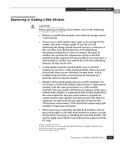
Servicing and Upgrading a DPE
3
Replacing or Adding a Disk Module
!
CAUTION
When replacing or adding a disk module, observe the following:
• Remove or install disk modules only while the storage system is powered up.
• Do not move a disk module that is part of an existing LUN to another slot in the storage system. If you do, you risk destroying the storage system...
Reference Guide - Page 59
Servicing and Upgrading a DPE
3
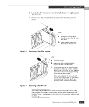
2. Locate the slot where you want to install the new or replacement disk module.
3. Remove the disk or disk filler module from the slot as shown below.
Latch
A. Grasp the filler module
handle so your thumb is on the latch.
B. Push the latch, and pull
the module from its slot.
Figure 3-3 Removing a Disk Filler...
Reference Guide - Page 60
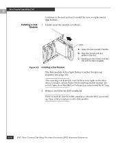
... and Upgrading a DPE
3
Installing a Disk Module
Continue to the next section to install the new or replacement disk module.
1. Gently insert the module as follows:
Latch
A. Grasp the disk module's handle. B. Align the module with the
guides in the slot. C. Gently push the module into the
slot until the latch engages.
Figure 3-5 Installing a Disk Module
The disk module Active light flashes...
Reference Guide - Page 63
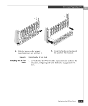
Servicing and Upgrading a DPE
3
A. Slide the latches on the fan pack
inward as shown, and hold them in.
B. Grasp the handles and gently pull
the pack from the enclosure.
Figure 3-8 Removing the SP Fan Pack
Installing the SP Fan Pack
1. At the front of the DPE, insert the replacement fan pack into the enclosure...
Reference Guide - Page 64
Servicing and Upgrading a DPE
3
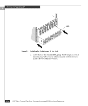
LED
Figure 3-9 Installing the Replacement SP Fan Pack 2. At the front of the deskside DPE, grasp the SP fan pack cover at its sides and push it onto its ballstud mounts with the louvers slanted downward as shown next.
3-16
EMC Fibre Channel Disk-Array Processor Enclosure (DPE) Hardware Reference
Reference Guide - Page 65
Servicing and Upgrading a DPE
3
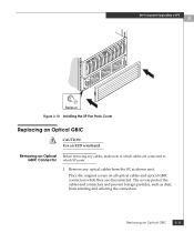
Ballstud Figure 3-10 Installing the SP Fan Pack Cover
Replacing an Optical GBIC
!
CAUTION
Use an ESD wristband.
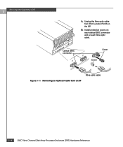
Removing an Optical GBIC Connector
Before removing any cables, make note of which cables are connected to which SP ports.
1. Remove any optical cables from the SP, as shown next.
Place the original covers on all optical cables and optical GBIC ...
Reference Guide - Page 66
Servicing and Upgrading a DPE
3
A. Unplug the fibre optic cable from Port A and/or Port B on the SP.
B. Install protective covers on each optical GBIC connector and on each fibre optic cable.
Optical GBIC connector
B
Cover
A
Cover
Fibre optic cable Figure 3-11 Removing an Optical Cable from an SP
3-18
EMC Fibre Channel Disk-Array Processor Enclosure (DPE) Hardware Reference
Reference Guide - Page 67
Servicing and Upgrading a DPE
3
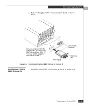
2. Remove the optical GBIC connector(s) from the SP as shown below.
B
A
While pressing inward on the retaining clips, pull the optical GBIC connector out of the SP. You may need to wiggle the connector to unseat it.
Retaining clip
Figure 3-12 Removing an Optical GBIC Connector from an SP
Optical GBIC connector
Retaining...
Reference Guide - Page 68
Servicing and Upgrading a DPE
3
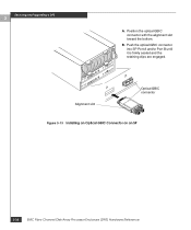
A. Position the optical GBIC connector with the alignment slot toward the bottom.
B. Push the optical GBIC connector into SP Port A and/or Port B until it is firmly seated and the retaining clips are engaged.
A
Alignment slot
B
Optical GBIC connector
Figure 3-13 Installing an Optical GBIC Connector on an SP
3-20
EMC Fibre Channel Disk-Array Processor Enclosure...
Reference Guide - Page 69
Servicing and Upgrading a DPE
3
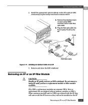
2. Install the appropriate optical cable(s) on the SP's optical GBIC connector(s) as previously noted and as shown below.
A. Remove the protective covers on each optical GBIC connector and on each fibre optic cable.
B. Plug the fibre optic cable into Port A and/or Port B on the SP.
Cover
Optical GBIC connector
B
A
Cover
Fibre optic cable
Figure 3-14 Installing ...
Reference Guide - Page 80
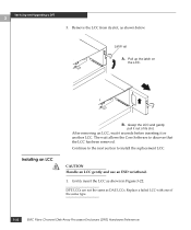
Servicing and Upgrading a DPE
3
3. Remove the LCC from its slot, as shown below.
Latch up
A. Pull up the latch on
the LCC.
Installing an LCC
!
B. Grasp the LCC and gently
pull it out of its slot. After removing an LCC, wait 6 seconds before inserting it or another LCC. The wait allows the Core Software to...