Dell PowerEdge 2200 driver and firmware
Related Dell PowerEdge 2200 Manual Pages
Download the free PDF manual for Dell PowerEdge 2200 and other Dell manuals at ManualOwl.com
Service Manual - Page 6
...Installation 4-16 Figure 4-17. System Board Assembly Removal 4-17 Figure 4-18. Removing the System Board Assembly From the Chassis . . . . 4-18 Figure 4-19. Microprocessor Module Retention Screws 4-19 Figure 4-20. Removing a Microprocessor Module
From a Retention Bracket 4-19 Figure 4-21. Removing a Microprocessor Module
From the System Board 4-20 Figure 4-22. Terminator Card...System Error ...
Service Manual - Page 9
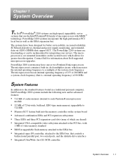
...• Integrated VGA-compatible video subsystem attached to the PCI bus, with
1 MB of video memory standard
• BIOS in upgradable flash memory attached to the EISA bus • Integrated super I/O controller, attached to the EISA bus, that controls a
bidirectional parallel port, two serial ports, and the diskette drive interface
• Integrated Ultra/Wide (fast-20) SCSI controller
System...
Service Manual - Page 10
... installing the PowerEdge 2200 systems in a rack, see the Dell PowerEdge 2200 Systems Rack Kit Installation Guide (P/N 87743).
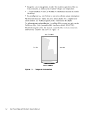
When following the text in this manual, assume that the location or direction relative to the computer is as shown in Figure 1-1.
back of computer
left side
right side
front of computer
Figure 1-1. Computer Orientation
1-2 Dell PowerEdge 2200 Systems Service Manual
Service Manual - Page 13
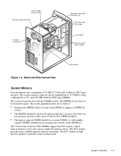
...-supply selector switch AC power input connector
I/O panel connectors
externally accessible drive bays (3)
SCSI hard-disk drive cage
SCSI cable
hard-disk-drive power cables
system board
Figure 1-4. Back/Left Side Internal View
System Memory
System memory has a minimum of 32 MB of 72-bit-wide, buffered, EDO-type memory. The system memory capacity can be expanded up to 512 MB by using combinations...
Service Manual - Page 14
.... The integrated SCSI controller attaches to the PCI bus to provide a high-performance SCSI bus. The integrated SCSI controller provides control for the three SCSI hard-disk drives in the SCSI hard-disk drive cage, the CD-ROM drive in the middle externally accessible drive bay, and a SCSI drive installed in the lower externally accessible drive bay.
1-6 Dell PowerEdge 2200 Systems Service Manual
Service Manual - Page 15
... Guide for additional SCSI addressing information. NOTE: Any narrow SCSI devices installed in the externally accessible drive bays will require SCSI ID numbers less than 7. When SCSI devices are shipped from Dell, the default SCSI ID numbers are assigned as follows:
• The computer's built-in SCSI controller is configured through the BIOS as
SCSI ID 7 (the default ID number for a host adapter...
Service Manual - Page 16
... the Dell-supplied 2-gigabyte (GB), 4-GB, and 9-GB SCSI hard-disk drives for the PowerEdge 2200 system.
• If you install an optional SCSI controller card to control the CD-ROM drive
and any other SCSI device in the externally accessible drive bays, you must enable termination for the SCSI controller card and the SCSI device at the end of the SCSI interface cable (preferably the CD-ROM drive...
Service Manual - Page 24
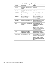
...
system to clear configura-
tion settings.
Enables/disables integrated video controller
Boots from BIOS card
Remove jumper and use EISA Configuration Utility to configure system.
Install jumper to enable integrated video controller.
Install jumper to boot system from BIOS expansion card.
Remove jumper to allow normal boot operation from BIOS.
1-16 Dell PowerEdge 2200 Systems Service Manual
Service Manual - Page 29
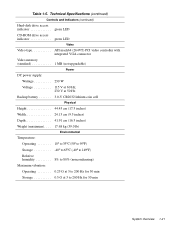
...Controls and Indicators (continued)
Hard-disk drive access indicator green LED CD-ROM drive access indicator green LED
Video
Video type ATI mach64 (264VT) PCI video controller with integrated VGA connector
Video memory (standard 1 MB (not upgradable)
Power
DC power... Operating 10° to 35°C (50° to 95°F) Storage 40° to 65°C (-40° to 149°F) Relative ...
Service Manual - Page 35
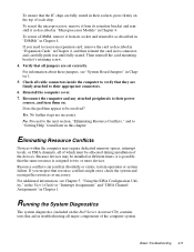
... its connector, and carefully push it in until fully seated. Then reinstall the card-mounting bracket's retaining screw. 4. Verify that all jumpers are set correctly. For information about these jumpers, see "System Board Jumpers" in Chapter 1. 5. Check all cable connectors inside the computer to verify that they are firmly attached to their appropriate connectors. 6. Reinstall...
Service Manual - Page 37
... Diagnostics" in Chapter 2.
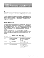
POST Beep Codes
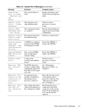
If the monitor cannot display error messages during the POST, the system may emit a series of...Error
Probable Causes
Invalid expansion-card ROM checksum
Improperly seated expansion card or the system needs rebooting.
Invalid BIOS ROM check- Corrupted BIOS firmware or
sum
defective system board.
DRAM refresh failure
Defective DIMMs or system board...
Service Manual - Page 38
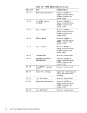
...the system board.
Invalid ROM copyright notice
Defective system board.
Unexpected interrupt
Improperly seated expansion card or the system needs rebooting.
Gate A20 failure
Defective system board.
Keyboard controller error
Defective DIMMs or system board. Reseat the DIMMs or replace the system board.
Gate A20 failure
Defective system board.
3-2 Dell PowerEdge 2200 Systems Service Manual
Service Manual - Page 39
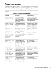
... firmware download failed
The BIOS is attempting to download embedded server management firmware.
Download of ESM firmware timed out.
Expansion ROM not initialized
Incorrect drive A type - Run Setup
Incorrect drive B type - Run Setup
Invalid CPU speed detected Check jumpers
The BIOS detected a resource conflict while configuring a Plug and Play ISA or PCI expansion card.
The diskette drive...
Service Manual - Page 40
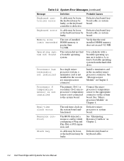
... on the system board malfunctioned.
Defective microprocessor or system board.
Resource conflict
The BIOS detected a resource conflict while configuring a Plug and Play ISA or PCI expansion card.
See "Eliminating Resource Conflicts" in Chapter 2.
Stuck key
A cable may be loose, Defective keyboard or or the keyboard may be keyboard cable. faulty.
3-4 Dell PowerEdge 2200 Systems Service Manual
Service Manual - Page 41
... or replace the DIMMs.
System timer error
A chip on the system board malfunctioned.
Defective microprocessor or system board.
Warning: IRQ not initialized
The BIOS detected a resource conflict while configuring a Plug and Play ISA or PCI expansion card.
See "Eliminating Resource Conflicts" in Chapter 2.
Warning: Processor is not installed in Processor 1 slot
No microprocessor module is...
Service Manual - Page 45
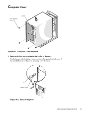
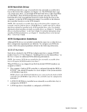
Computer Cover
cover-mounting screws (4)
handle
Figure 4-1. Computer Cover Removal
1. Remove the four screws along the back edge of the cover. Use the key provided with the system to remove the special keylock screw if it is installed in one of the cover-mounting screw locations.
key keylock screw
Figure 4-2. Security Keylock
Removing and Replacing Parts 4-3
Service Manual - Page 50
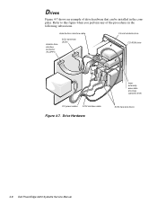
... when you perform any of the procedures in the following subsections.
diskette drive interface cable
diskette drive interface connector (FLOPPY)
SCSI connector (SCSI)
3.5-inch diskette drive CD-ROM drive
DC power cables SCSI interface cable
Figure 4-7. Drive Hardware
lower externally accessible drive bay (optional drive)
SCSI hard-disk drives
4-8 Dell PowerEdge 2200 Systems Service Manual
Service Manual - Page 53
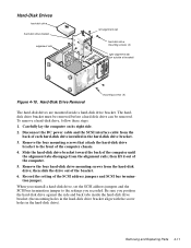
...; then lift it out of the computer.
5. Remove the four hard-disk drive mounting screws from the hard-disk drive; then slide the drive out of the bracket.
6. Record the setting of the SCSI address jumpers and SCSI bus termination jumper.
When you reinstall a hard-disk drive, set the SCSI address jumpers and the SCSI bus termination jumper to the settings you recorded. Be sure you position the hard...
Service Manual - Page 56
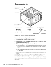
...installed
plunger
plunger
barrel
back wall of chassis
Figure 4-13. System Cooling-Fan Removal
system cooling fan
To remove the system cooling fan, follow these steps:
1. Carefully lay the computer on its right side.
2. Disconnect the system cooling-fan cable from the FAN connector on the system board... push in the plunger to lock the fastener.
4-14 Dell PowerEdge 2200 Systems Service Manual
Service Manual - Page 58
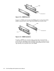
...is released from its socket. Then lift the DIMM away from the socket.
DIMM
cutout
securing clip (2)
2.
1.
Figure 4-16. DIMM Installation
To replace a DIMM, press outward on the securing clips at each end of the socket until they snap open. Orient the DIMM to... while pulling up on the securing clips until they lock around the ends of the DIMM.
4-16 Dell PowerEdge 2200 Systems Service Manual