Gigabyte GA-7PCSLD driver and firmware

Related Gigabyte GA-7PCSLD Manual Pages
Download the free PDF manual for Gigabyte GA-7PCSLD and other Gigabyte manuals at ManualOwl.com
Manual - Page 54
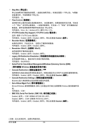
...; VT-UTF8 Combo Key Support ( VT-UTF8 Combo VT-UTF8 Combo Enabled Disabled Enabled Recorder Mode Enabled Disabled Resolution 100x31 100x31 Enabled Disabled Legacy OS Redirection Resolution 80x24/80X25。 Serial Port for Out-of-Bnad Management/Windows Emerency Service (EMS Windows Console Redirection Enabled Disabled Disabled Console Redirection Settings Enter Out-of-Bnad...
Manual - Page 3
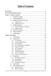
... Setting 29
Chapter 2 BIOS Setup 34 2-1 The Main Menu 36 2-2 Advanced Menu 38
2-2-1 PCI Configuration...39 2-2-2 Trusted Computing (Optioanl 40 2-2-3 CPU Configuration 41 2-2-3-1 CPU Power Management Configuration 44 2-2-4 Runtime Error Logging 46 2-2-5 SATA Configuration 47 2-2-6 SAS Configuration 48 2-2-7 Info Report Configuration 49 2-2-8 Super IO Configuration 50 2-2-9 Serial Port...
Manual - Page 5
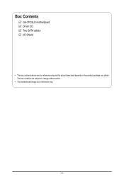
Box Contents
GA-7PCSLD motherboard Driver CD Two SATA cables I/O Shield
• The box contents above are for reference only and the actual items shall depend on the product package you obtain. The box contents are subject to change without notice.
• The motherboard image is for reference only.
- 5 -
Manual - Page 7
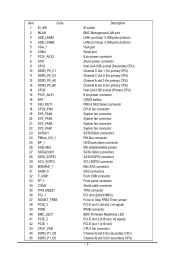
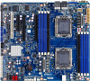
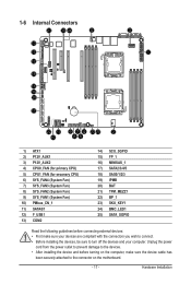
... BMC Management LAN port LAN1 port (top) / USB ports (bottom) LAN2 port (top) / USB ports (bottom) VGA port Serial port 8 pin power connector 24-pin power connector Intel LGA1356 socket (Secondary CPU) Channel C slot 1 (for primary CPU) Channel C slot 0 (for primary CPU) Channel A slot 0 (for primary CPU) Channel B slot 0 (for primary CPU) Intel LGA1356 socket (Primary CPU) 8 pin power connector...
Manual - Page 9
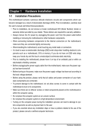
... a motherboard, CPU or memory. If you do not have an ESD wrist strap, keep your hands dry and first touch a metal object to eliminate static electricity. • Prior to installing the motherboard, please have it on top of an antistatic pad or within an electrostatic shielding container. • Before unplugging the power supply cable from the motherboard, make...
Manual - Page 10
...138;
USB
ŠŠ
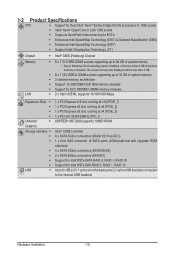
1 x PCI Express x16 slot, running at x16 (PCIE_1) 1 x PCI Express x8 slot, running at x8 (PCIE_2) 1 x PCI Express x8 slot, running at x4 (PCIE_3) 1 x PCI slot 32-Bit/33MHz (PCI_1) ASPEED® AST2300 supports 16MB VRAM
Intel® C606 controller 4 x SATA 3Gb/s connectors (SAS0/1/2/3/via SCU) 1 x mini SAS connector (4 SATA ports (3Gb/s)/optional with Upgrade ROM attached...
Manual - Page 11
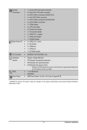
... temperature detection ŠŠ CPU/System fan speed detection ŠŠ CPU/System fan speed control * Whether the CPU/system fan speed control function is supported will depend on
the CPU/system cooler you install. ŠŠ 1 x 64 Mbit flash ŠŠ AMI BIOS ŠŠ CEB Form Factor; 12 inch x 10.5 inch, 8 layers PCB
* GIGABYTE reserves the right to make...
Manual - Page 12
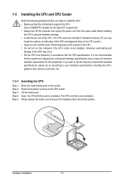
... guidelines before you begin to install the CPU: • Make sure that the motherboard supports the CPU.
(Go to GIGABYTE's website for the latest CPU support list.) • Always turn off the computer and unplug the power cord from the power outlet before installing
the CPU to prevent hardware damage. • Locate the pin one of the CPU. The CPU cannot be inserted if oriented...
Manual - Page 13
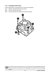
... below to correctly install the CPU cooler on the motherboard. Step 1. Attach the heat sink clip to the processor socket. Step 2. Secure the cooing fan with screws.. Step 3. Connect processor fan can cable to the processor fan connector.
1 1
1 1
2
Use extreme care when removing the CPU cooler because the thermal grease/tape between the
CPU cooler and CPU may adhere to...
Manual - Page 14
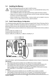
... you begin to install the memory: • Make sure that the motherboard supports the memory. It is recommended that memory of the
same capacity, brand, speed, and chips be used. (Go to GIGABYTE's website for the latest supported memory speeds and memory modules.) • Always turn off the computer and unplug the power cord from the power outlet before installing the memory to prevent hardware...
Manual - Page 15
..., and and DDR3_P0_C1 sockets for primary CPU; install DDR3_P1_D0, DDR3_P1_E0, DDR3_P1_F0, and DDR3_P1_F1 for secondary CPU
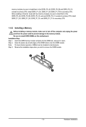
1-4-2 Installing a Memory
Before installing a memory module, make sure to turn off the computer and unplug the power cord from the power outlet to prevent damage to the memory module. Be sure to install DDR3 DIMMs on this motherboard. Installation Step: Step 1. Insert the DIMM...
Manual - Page 16
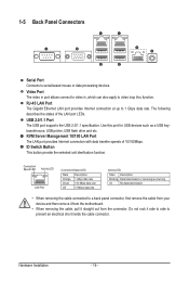
... LAN Port The Gigabit Ethernet LAN port provides Internet connection at up to 1 Gbps data rate. The following describes the states of the LAN port LEDs.
USB 2.0/1.1 Port The USB port supports the USB 2.0/1.1 specification. Use this port for USB devices such as a USB keyboard/mouse, USB printer, USB flash drive and etc. KVM Server Management 10/100 LAN Port The LAN port provides Internet connection...
Manual - Page 17
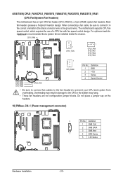
... 4) CPU0_FAN (for primary CPU) 5) CPU1_FAN (for seconary CPU) 6) SYS_FAN4 (System Fan...installing the devices, be sure to turn off the devices and your computer. Unplug the power
cord from the power outlet to prevent damage to the devices. • After installing the device and before turning on the computer, make sure the device cable has
been securely attached to the connector on the motherboard...
Manual - Page 18
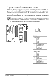
... on the motherboard. Before connecting the power connector, first make sure the power supply is turned off and all devices are properly installed. The power connector possesses a foolproof design. Connect the power supply cable to the power connector in the correct orientation. The 12V power connector mainly supplies power to the CPU. If the 12V power connector is not connected, the computer will...
Manual - Page 19
... ATX_12V
ATX1
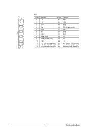
Pin No. 1 2 3 4 5 6 7 8 9 10 11 12
Definition
Pin No.
3.3V
13
3.3V
14
GND
15
+5V
16
GND
17
+5V
18
GND
19
Power Good
20
5VSB (stand by +5V)
21
+12V
22
+12V (Only for 2x12-pin ATX) 23
3.3V (Only for 2x12-pin ATX) 24
Definition 3.3V... On/Off) GND GND GND -5V +5V +5V +5V (Only for 2x12-pin ATX) GND (Only for 2x12-pin ATX)
FDD
IDE
- 19 -
Hardware Installation
Manual - Page 20
... insertion design. When connecting a fan cable, be sure to connect it in the correct orientation (the black connector wire is the ground wire). The motherboard supports CPU fan speed control, which requires the use of a CPU fan with fan speed control design. For optimum heat dissipSaYtSio_FnA,Nit4is recommended that a system fan be installed inside the chassis.
CPU1_FAN
1 CPU1_FAN...
Manual - Page 21
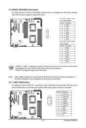
... compatible with SATA 3Gb/s standard. Each SATA connector supports a single SATA device.
7 1
G.QBOFM
When SATA_DOM0/1 jumper are set to Normal Mode:
Pin No. 1 2 3 4 5 6 7
Definition GND TXP TXN GND RXN RXP GND
When SATA_DOM0/1 Jumper are set to 1-2 pin: Pin No. Definition
1 GND 2 TXP 3 TXN 4 GND 5 RXN 6 RXP 7 P5V
• A RAID 0 or RAID 1 configuration requires at least two hard drives. If...
Manual - Page 22
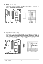
... is stands for Serial General Purpose Input/Output which is a 4-signal (or 4-wire) bus used between a Host Bus Adapter (HBA) and a backplane. Out of the 4 signals, 3 are driven by the HBA and 1 is driven by the backplane. Typically, the HBA is a storage controller located inside a server, desktop, rack or workstation computer that interfaces with Hard disk drives (HDDs) to store...
Manual - Page 27
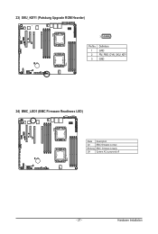
23) SKU_KEY1 (Patsburg Upgrade ROM Hearder)
3
1
Pin No. 1 2 3
Definition GND FM_PBG_DYN_SKU_KEY GND
24) BMC_LED1 (BMC Firmware Readiness LED)
State Description
On
BMC firmware is initial
Blinking BMC firmware is ready
Off
System AC is powered off
- 27 -
Hardware Installation
Manual - Page 42
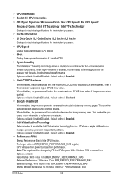
... installed CPU speed. 64-bit
Display the supported infprmation of installed CPU. Hyper-threading
The Intel Hyper Threading Technology allows a single processor to execute two or more separate threads concurrently. When hyper-threading is enabled, multi-threaded software applications can execute their threads, thereby improving performance. Options available: Enabled/Disabled. Default setting...