Gigabyte GA-7PESVL driver and firmware

Related Gigabyte GA-7PESVL Manual Pages
Download the free PDF manual for Gigabyte GA-7PESVL and other Gigabyte manuals at ManualOwl.com
Manual - Page 5
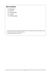
Box Contents
Motherboard Driver CD Two SATA cables I/O Shield CPU Power cables
• The box contents above are for reference only and the actual items shall depend on the product package you obtain. The box contents are subject to change without notice.
• The motherboard image is for reference only.
- 5 -
Manual - Page 8
... BIOS_RVCR1
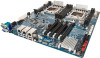
PCI-E x16 slot Intel C600 series upgrade key PCI-E x16 slot (Running at x8) TPM module connector ASPEED 2300 BMC chipset BMC firmware readiness LED PMBUS Select jumper Chassis intrusion header PS2 Keyboard/Mouse header S3 Power On Select jumper Force to Stop FRB Timer jumper Clear CMOS jumper ME recovery jumper Clearning supervisor password jumper BIOS recovery jumper...
Manual - Page 10
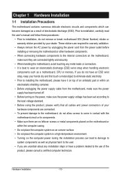
... a motherboard, CPU or memory. If you do not have an ESD wrist strap, keep your hands dry and first touch a metal object to eliminate static electricity. • Prior to installing the motherboard, please have it on top of an antistatic pad or within an electrostatic shielding container. • Before unplugging the power supply cable from the motherboard, make...
Manual - Page 11
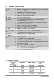
...) 2 x PCI Express x16 slot, running at x8 (Gen3/PCIE_2/PCIE_4) ASPEED® AST2300 supports 16MB VRAM
Intel® C602 controller 2 x SATA 6Gb/s connectors (SATA0/SATA1) 4 x SATA 3Gb/s connectors (SATA2/SATA3/SATA4/SATA5) 4 x SAS connectors (4 additional SATA ports (3Gb/s) /option SAS ports (3Gb/s) with upgrade key required) Support for Intel RSTe SATA RAID 0, RAID 1 Up to 4 USB 2.0 ports (2 on...
Manual - Page 12
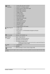
... VGA port
ŠŠ ASPEED® AST2300 BMC chip
ŠŠ System voltage detection ŠŠ CPU/System temperature detection ŠŠ CPU/System fan speed detection ŠŠ CPU/System fan speed control * Whether the CPU/system fan speed control function is supported will depend on
the CPU/system cooler you install. ŠŠ 1 x 64 Mbit flash ŠŠ AMI BIOS Š...
Manual - Page 13
... not recommended
that the system bus frequency be set beyond hardware specifications since it does not meet the standard requirements for the peripherals. If you wish to set the frequency beyond the standard specifications, please do so according to your hardware specifications including the CPU, graphics card, memory, hard drive, etc.
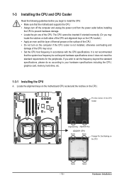
1-3-1 Installing the CPU
A. Locate the alignment keys on...
Manual - Page 14
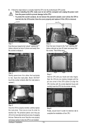
... steps below to correctly install the CPU into the motherboard CPU socket. •• Before installing the CPU, make sure to turn off the computer and unplug the power cord from the power outlet to prevent damage to the CPU.
•• To protect the socket contacts, do not remove the protective plastic cover unless the CPU is inserted into the...
Manual - Page 15
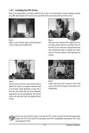
... steps below to correctly install the CPU cooler on the motherboard. (Actual installation process may differ depending the CPU cooler to be used. Refer to the user's manual for your CPU cooler.)
Step 1: Apply an even and thin layer of thermal grease on the surface of the installed CPU.
Step 2: Place the cooler atop the CPU, aligning the four mounting...
Manual - Page 16
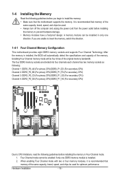
... you begin to install the memory: • Make sure that the motherboard supports the memory. It is recommended that memory of the
same capacity, brand, speed, and chips be used. • Always turn off the computer and unplug the power cord from the power outlet before installing
the memory to prevent hardware damage. • Memory modules have a foolproof design. A memory module can be...
Manual - Page 17
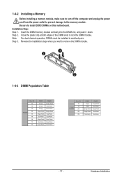
1-4-2 Installing a Memory
Before installing a memory module, make sure to turn off the computer and unplug the power cord from the power outlet to prevent damage to the memory module. Be sure to install DDR3 DIMMs on this motherboard. Installation Step: Step 1. Insert the DIMM memory module vertically into the DIMM slot, and push it down. Step 2. Close the plastic clip at both edges...
Manual - Page 18
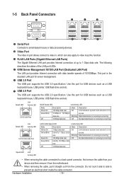
... 10/100 LAN Port (Dedicated LAN Port) The LAN port provides Internet connection with data transfer speeds of 10/100Mbps. This port is the decated LAN port for server management. USB 3.0 Port The USB port supports the USB 3.0 specification. Use this port for USB devices such as a USB keyboard/mouse, USB printer, USB flash drive and etc. USB 2.0 Port
The USB port supports the USB 2.0 specification...
Manual - Page 19
...18 26
1
25 17
4
19
7
8
20
9
10
5
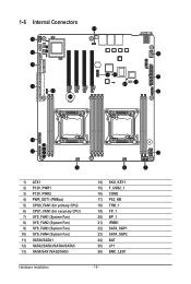
1) ATX1 2) P12V_PWR1 3) P12V_PWR2 4) PWR_DET1 (PMBus) 5) CPU0_FAN1 (for primary CPU) 6) CPU1_FAN1 (for seconary CPU) 7) SYS_FAN1 (System Fan) 8) SYS_FAN2 (System Fan) 9) SYS_FAN3 (System Fan) 10) SYS_FAN4 (System Fan) 11) SATA0/SATA1 12) SATA2/SATA3...BP_1 21) IPMB1 22) SATA_SGP1 23) SATA_SGP2 24) BAT 25) JP1 26) BMC_LED1
Hardware Installation
- 19 -
3 2
Manual - Page 20
... the connectors you wish to connect. • Before installing the devices, be sure to turn off the devices and your computer. Unplug the
power cord from the power outlet to prevent damage to the devices. • After installing the device and before turning on the computer, make sure the device cable has
been securely attached to the connector on the motherboard.
- 20 -
Hardware...
Manual - Page 21
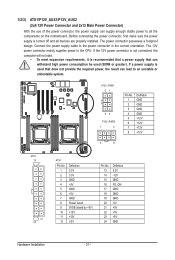
... on the motherboard. Before connecting the power connector, first make sure the power supply is turned off and all devices are properly installed. The power connector possesses a foolproof design. Connect the power supply cable to the power connector in the correct orientation. The 12V power connector mainly supplies power to the CPU. If the 12V power connector is not connected, the computer will...
Manual - Page 22
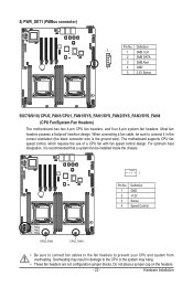
... wire). The motherboard supports CPU fan speed control, which requires the use of a CPU fan with fan speed control design. For optimum heat dissipation, it is recommended that a system fan be installed inside the chassis.
1
Pin No. 1 2 3 4
Definition GND +12V Sense Speed Control
SYS_FAN1 SYS_FAN2 SYS_FAN3 SYS_FAN4
CPU0_FAN1
CPU1_FAN1
• Be sure to connect fan cables to the fan...
Manual - Page 23
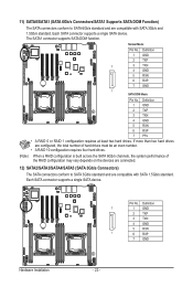
... SATA connector supports a single SATA device. The SATA1 connector supports SATA DOM function.
Normal Mode:
SATA0 SATA1
Pin No. Definition
1 GND
2 TXP
7
3 TXN
4 GND
5 RXN
6 RXP
7 GND
1 SATA DOM Mode:
Pin No. Definition
1 GND
2 TXP
3 TXN
4 GND
5 RXN
6 RXP 7 P5V
DEBUG PORT
• A RAID 0 or RAID 1 configuration requires at least two hard drives. If more than two hard drives...
Manual - Page 24
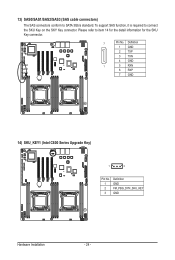
13) SAS0/SAS1/SAS2/SAS3 (SAS cable connectors)
The SAS connectors conform to SATA 3Gb/s standard. To support SAS function, it is required to connect the SKU Key on the SKY Key connector....
1 GND
2 TXP
3 TXN
4 GND
SAS0 SAS1 SAS2 SAS3
1
5 RXN
6 RXP
7 GND
14) SKU_KEY1 (Intel C600 Series Upgrade Key)
1
3
Pin No. 1 2 3
Definition GND FM_PBG_DYN_SKU_KEY GND
Hardware Installation
- 24 -
Manual - Page 30
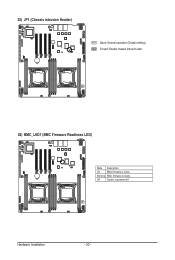
25) JP1 (Chassis intrusion Header)
Open: Normal operation (Default setting) Closed: Enable chassis intrusion alter.
26) BMC_LED1 (BMC Firmware Readiness LED)
State Description
On
BMC firmware is initial
Blinking BMC firmware is ready
Off
System is powered off
Hardware Installation
- 30 -
Manual - Page 40
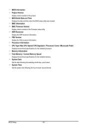
... BIOS setup utility was created. BMC Information BMC Firmware Version Display version number of the Firmware setup utility. SDR Reversion Display the SDR reversion information. FRU Version Display the FRU reversion information. Processor Information CPU Type/ Max CPU Speed/ CPU Signature / Processor Cores / Microcode Patch Displays the technical specifications for the installed processor. Memory...
Manual - Page 51

... value 7 into MSR_ENERGY_PERFORMANCE_BIAS Balanced Energy: Write value 11 into MSR_ENERGY_PERFORMANCE_BIAS Energy Efficient: Write value 15 into MSR_ENERGY_PERFORMANCE_BIAS Default setting is Performance.
(Note)
This item is present only if you install a CPU that supports this feature. For more information about
Intel CPUs' unique features, please visit Intel's website.
- 51 -
BIOS Setup