Gigabyte GS-R12T4H2 driver and firmware
Drivers and firmware downloads for this Gigabyte item

Related Gigabyte GS-R12T4H2 Manual Pages
Download the free PDF manual for Gigabyte GS-R12T4H2 and other Gigabyte manuals at ManualOwl.com
Manual - Page 3
...GS-R12T4H2-RH 29 Rear View of GS-R12T4H2-RH 30 Front Panel LED Indicator 31 LAN port LED Indicator ...33 Hard Disk Drive LED Description 34 GC-BS14U-RH Back plane board Components 35 System Block Diagram 36 Connector Icon Description 37
Motherboard Placement and Jumper Setting 38
GA-7TTSE-RH Motherboard Component 38 Jumper Setting ...40 Expansion Card Components Description 42
BIOS Setup...
Manual - Page 6
... of fire, use only No. 26 AWG or larger telecommunications line cord. * Do not plug a modem or telephone cable into the network interface controller (NIC) receptacle. * Disconnect the modem cable before opening a product enclosure, touching or installing internal components, or touching an uninsulated modem cable or jack. * Do not use a telephone line to report a gas leak while you are...
Manual - Page 7
... or coin-telephone service. The FCC also requires the transmitter of a FAX transmission be properly identified (per FCC Rules Part 68, Sec. 68.381 (c) (3)). / for Canadian users only /
Canadian Department of Communications Compliance Statement
This digital apparatus does not exceed the Class A limits for radio noise emissions from digital apparatus as set out in...
Manual - Page 8
... for a class A digital device pursuant Part 15 of the FCC Rules. These limits are designed to provide reasonable protection against harmful interference when the equipment is operated in a commercial environment. This equipment generate, uses, and can radiate radio frequency energy, and if not installed and used in accordance with the instructions, may cause harmful...
Manual - Page 9
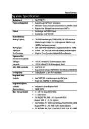
... Specification
Feature Summary
Motherboard Processor Supported
Chipset
System Memory: Memory Capacity
Memory Type DIMM Size Error Correction Expansion Slot Two riser cards (optional) Full-height: Low-profile SATA RAID controller
Cooling Fans: Integrated LANs: Controller
Integrated Graphics: Controller Graphics Memory Mass Storage System
GA-7TTSE-RH Supports dual Intel®...
Manual - Page 11
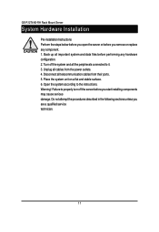
GS-R12T4H2-RH Rack Mount Server
System Hardware Installation
Pre-installation Instructions Perform the steps below before you open the server or before you remove or replace any component. 1. Back up all important system and data files before performing any hardware configuration. 2. Turn off the system and all the peripherals connected to it. 3. Unplug all cables from...
Manual - Page 13
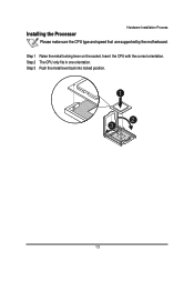
Installing the Processor
Hardware Installation Process
Please make sure the CPU type and speed that are supported by the motherboard.
Step 1 Raise the metal locking lever on the socket. Insert the CPU with the correct orientation. Step 2 The CPU only fits in one orientation. Step 3 Push the metal lever back into locked position.
1
2 3
13
Manual - Page 14
GS-R12T4H2-RH Rack Mount Server
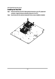
Installing the Heat Sink
Step 1 Place the Heat Sink on the CPU. Before putting the heat sink on the CPU, please well remember to apply the thermal conductivity compound on the CPU.
Step 2 Seat the heat sink in the retention modules with the four screws. Installation completed.
1
5
3
5
4
1
3
1
12 4
1
2
14
Manual - Page 15
GS-R12T4H2-RH Rack Mount Server
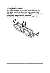
Installing the Memeory Module
Step 1. Insert the DIMM memory module vertically into the DIMM slot, and push it down. Step 2. Close the plastic clip at both edges of the DIMM slots to lock the ...
Manual - Page 19
Hardware Installation Process
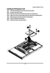
Installing the PCI Expansion Card
Step 1 Lift the riser bracket slightly, then pull it out from the server chassis. Step 2 Loosen the riser bracket screws. Step 3 Attach the mini card to the riser bracket and ecure the mini card with screws. Step 4 Attach the mini card to the riser bracket the other side. Secure the...
Manual - Page 21
GS-R12T4H2-RH Rack Mount Server
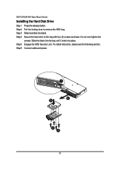
Installing the Hard Disk Drive
Step 1 Press the release button. Step 2 Pull the locking lever to remove the HDD tray. Step 3 Slide hard disk into blank. Step 4 Secure the hard drive to the tray with four (4) screws as shown. Do not over tighten the
screws. Slide the blank into the bay until...
Manual - Page 22
Hardware Installation Process
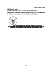
HDD Security Lock
The HDD bays incorporate a security screw to prevent accidental HDD release. To engage the lock, turn the security screw clock-wise toward the Lock symbol. To disengage the lock, turn the security screw counter clock-wise toward the Unlock symbol as shown.
22
Manual - Page 23
GS-R12T4H2-RH Rack Mount Server
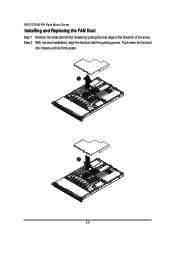
Installing and Replacing the FAN Duct
Step 1 Remove the airducts from the chassis by pulling the rear edge in the direction of the arrow Step 2 With fan duct installation, align the fan duct with the guiding groove. Push down the fan duct
into chassis until its firmly seats.
1
0.3571
2
0.3571
23
Manual - Page 24
Hardware Installation Process
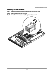
Replacing the FAN Assemblly
Step 1 Remove thefan assemble pulling the rear edge in the direction of the arrow Step 2 Lift up the fan assembly from the chassis. Step 3 Reverse the previous steps to install the replacement fan assembly.
24
Manual - Page 26
Hardware Installation Process
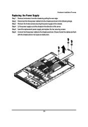
Replacing the Power Supply
Step 1 Remove the fanduct from the chassis by pulling the rear edge. Step 2 Disconnect the three power cables from the chassis as shown in the following image. Step 3 Remove the thress screws securing the power supply to the chassis. Step 4 Lift the power supply out of the chassis in the...
Manual - Page 29
... Mount Server
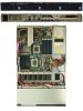
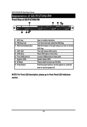
Appearance of GS-R12T4H2-RH
Front View of GS-R12T4H2-RH
5
6
78 9
4
1
23
1. HDD bay 2. HDD bay lock 3. HDD front release button
4. HDD LED 5. ODD drive 6. Front USB ports x2 7. System LEDs 9. ID Button 9. Power Button
Open to install a hard drive. Turn this to lock and unlock the HDD bay. Slide this release to the right and pull...
Manual - Page 30
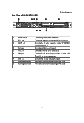
... View of GS-R12T4H2-RH
1
23 4
8
System Appearance
9
㕣
56
7
1. Power Module
Connect the power cable to the socket.
2. PS/2 port
Connect the keyboard and mouse devices to this port.
3. GLAN port
Connect a RJ-45 jack to this port to link to a 10/100/1000
Megabit Ethernet LAN.
4. Serial port
Connect serial devices to this port.
5. VGA port
Connect the monitor device to this...
Manual - Page 41
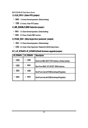
... jumper)
1
1-2 Close: Normal operation. (Default setting)
1
2-3 Close: Clear Supervisor Password in BIOS setup menu.
6/7 ) JP_STRAP2/ JP_STRAP8 (PilotII firmware upgrade jumper)
JP_STRAP2 JP_STRAP8 Descripeion
1
1
Boot from BMC BOOT SPI Interface. (Default setting)
1
1
Boot From BMC LPC BOOT ROM interface.
1
1
Boot From internal ROM(Scratchpad Registers)
1
1
Boot From internal...
Manual - Page 42
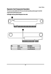
Expansion Card Components Description
Jumper Setting
The two riser cards installed in the PCI riser card bracket assembly povides support for both fullheoght and low-profile expansion cards.
Full height and low profile PCI Express riser cards
1
2
No.
Code
Description
1
PCI-E_X16_1
Full-height riser slot
2
PCI-E_2
Low-profile riser slot
42
Manual - Page 63
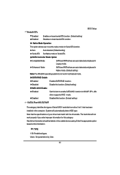
... Disabled
Enabled SATA RAID function. Disable this function. (Default setting)
SATA AHCI Enable Enabled
Disabled
Set this item to enable SATA AHCI function for WinXP-SP1+IAA driver supports AHCI mode.
Disabled this function. (Default setting)
SATA Port 0/1/2/3/4/5
The category identifies the types of Serial SATA hard disk from drive 0 to 5 that has been installed in the computer. System will...