Gigabyte GS-R22T61 driver and firmware


Related Gigabyte GS-R22T61 Manual Pages
Download the free PDF manual for Gigabyte GS-R22T61 and other Gigabyte manuals at ManualOwl.com
Manual - Page 3

...12 CPU Installation ...13 Heat Sink Installation ...14 Memory Installation ...15 PCI Expansion Card Installation (GC-RLE2N-RH/GC-RFE2N-RH 18 PCI Expansion Card Installation (GC-RFX2N-RH/Optional 20 GS-R22T81-RH Hard Disk Drive Installation 22 GS-R22T61-RH Hard Disk Drive Installation 23 FAN Duct Removal and Installation 24
Appearance of GS-R22T61-RH/GS-R22T81-RH 25
Front View of GS-R22T61-RH...
Manual - Page 6
... of fire, use only No. 26 AWG or larger telecommunications line cord. * Do not plug a modem or telephone cable into the network interface controller (NIC) receptacle. * Disconnect the modem cable before opening a product enclosure, touching or installing internal components, or touching an uninsulated modem cable or jack. * Do not use a telephone line to report a gas leak while you are...
Manual - Page 7

... or coin-telephone service. The FCC also requires the transmitter of a FAX transmission be properly identified (per FCC Rules Part 68, Sec. 68.381 (c) (3)). / for Canadian users only /
Canadian Department of Communications Compliance Statement
This digital apparatus does not exceed the Class B limits for radio noise emissions from digital apparatus as set out in...
Manual - Page 8
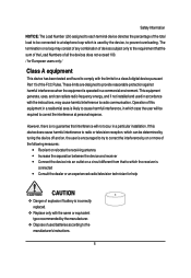
... for a class A digital device pursuant Part 15 of the FCC Rules. These limits are designed to provide reasonable protection against harmful interference when the equipment is operated in a commercial environment. This equipment generate, uses, and can radiate radio frequency energy, and if not installed and used in accordance with the instructions, may cause harmful...
Manual - Page 9
...
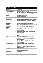
Processor Supported
Chipset
System Memory:
Memory Capacity
Memory Type
DIMM Size
Error Correction:
Riser Slot
Full height riser card:
Full height riser card: (Optional)
Low-profile riser card:
SATA RAID controller...
Manual - Page 11

GS-R22T61-RH/GS-R22T81-RH Rack Mount Server
System Hardware Installation
Pre-installation Instructions Perform the steps below ...cables from the power outlets. 4. Disconnect all telecommunication cables from their ports. 5. Place the system unit on a flat and stable surface. 6. Open the system according to the instructions. Warning! Failure to properly turn off the server before you start installing...
Manual - Page 12

Chassis Removal and Installation
Step 1 Step 2 Step 3 Step 4
Remove the screw on the chassis. Slide toward the top chassis cover. Lift up to remove the top chassis cover. Reverse Step 1, ,2, 3 to replace the chassis cover
Hardware Installation Process
3
1
2
12
Manual - Page 13

GS-R22T61-RH/GS-R22T81-RH Rack Mount Server
CPU Installation
Please make sure the CPU type and speed that are supported by the motherboard.
Step 1 Raise the metal locking lever on the socket. Insert the CPU with the correct orientation. Step 2 The CPU only fits in one orientation. Step 3 Push the metal lever back into locked position.
1 2
3
13
Manual - Page 14

Heat Sink Installation
Hardware Installation Process
Step 1 Place the Heat Sink on the CPU. Before putting the heat sink on the CPU, please well remember to apply the thermal conductivity compound on the CPU.
Step 2 Seat the heat sink in the retention modules with the four screws. Installation completed.
2
1
2
2
1
12
2
1
2
1
2
14
Manual - Page 15

GS-R22T61-RH/GS-R22T81-RH Rack Mount Server
Memory Installation
Step 1. Insert the DIMM memory module vertically into the DIMM slot, and push it down. Step 2. Close the plastic clip at both edges of the DIMM slots to lock the ...
Manual - Page 16
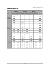
U-DIMM Population Table
Hardware Installation Process
Interleave
Channel A
Channel B
Channel C
mode
DIMMA1/D1 DIMMA2/D2 DIMMB1/E1 DIMMB2/E2 DIMMC1/F1 DIMMC2/F2
Total Memory
Single Channel
Dual Channel
1GB 2GB 4GB 1GB 2GB 4GB 1GB 2GB 4GB
1GB 2GB 4GB
1GB 2GB 4GB 1GB 2GB 4GB
1GB 2GB 4GB
...
Manual - Page 18

Hardware Installation Process
PCI Expansion Card Installation (GC-RLE2N-RH/GC-RFE2N-RH)
Step 1 Loosen the riser bracket screws which attached on on the system. Step 2 Loosen the rest riser bracket bracket screws. Step 3 Lift the riser bracket slightly, then pull it out from the server chassis. Step 4 Slide the expansion card into the slot until...
Manual - Page 20

Hardware Installation Process
PCI Expansion Card Installation (GC-RFX2N-RH/Optional)
Step 1 Step 2 Step 3 Step 4 Step 5 Step 6 Step 7 Step 8
Loosen the riser bracket screws which attached on on the system. Loosen the rest riser bracket bracket screws. Lift the riser bracket slightly, then pull it out from the server chassis. Attach the PCI-E card to the riser...
Manual - Page 22

Hardware Installation Process
GS-R22T81-RH Hard Disk Drive Installation
Step 1 Press the release button. Step 2 Pull the blank out of the drive bay. Step 3 Place hard disk into blank. Step 4 Secure it with screws.
Slide the blank into the bay until it locks into place. Connect cable and power.
2 1
3 4
4
22
Manual - Page 23
GS-R22T61-RH/GS-R22T81-RH Rack Mount Server
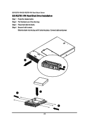
GS-R22T61-RH Hard Disk Drive Installation
Step 1 Step 2 Step 3 Step 4
Press the release button. Pull the blank out of the drive bay. Place hard disk into blank. Secure it with screws. Slide the blank into the bay until it locks into place. Connect cable and power.
2 1
4
3
4
23
Manual - Page 24
Hardware Installation Process
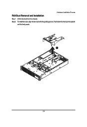
FAN Duct Removal and Installation
Step 1 Lift the fan duct from the chassis. Step 2 To install fan duct, align the fan duct with the guiding groove. Push down the fan duct into system
until its firmly seats.
1
24
Manual - Page 25
GS-R22T61-RH/GS-R22T81-RH Rack Mount Server
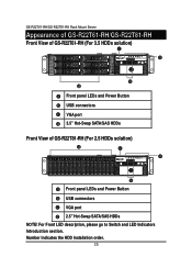
Appearance of GS-R22T61-RH/GS-R22T81-RH
Front View of GS-R22T61-RH (For 3.5 HDDs solution)
2
5
1
4
0
3
Front panel LEDs and Power Button USB connectors VGA port 3.5" Hot-Swap SATA/SAS HDDs
Front View of GS-R22T81-RH (For 2.5 HDDs solution)
0 1 2 3 4 5 6 7 8 9 10 11 12 1314 15
Front panel LEDs and Power Button
USB connectors
VGA port 2.5" Hot-Swap...
Manual - Page 40
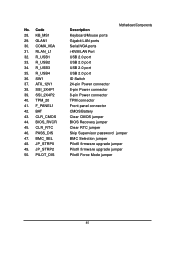
... ports Gigabit LAN ports Serial/VGA ports i-KVM LAN Port USB 2.0 port USB 2.0 port USB 2.0 port USB 2.0 port ID Switch 24-pin Power connector 8-pin Power connector 8-pin Power connector TPM connector Front panel connector CMOS Battery Clear CMOS jumper BIOS Recovery jumper Clear RTC jumper Skip Supervisor password jumper BMC Selection jumper PilotII firmware upgrade jumper PilotII firmware upgrade...
Manual - Page 42
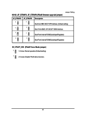
... firmware upgrade jumper)
JP_STRAP2 JP_STRAP8 Descripeion
1
1
Boot from BMC BOOT SPI Interface. (Default setting)
1
1
Boot From BMC LPC BOOT ROM interface.
1
1
Boot From internal ROM(Scratchpad Registers)
1
1
Boot From internal ROM(Scratchpad Registers)
50 ) PILOT_DIS (PilotII Force Mode jumper)
1
1-2 close: Normal operation (Default setting)
1
2-3 close: Disable PilotII device...
Manual - Page 67
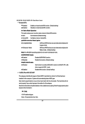
... Disabled
Enabled SATA RAID function. Disable this function. (Default setting)
SATA AHCI Enable Enabled
Disabled
Set this item to enable SATA AHCI function for WinXP-SP1+IAA driver supports AHCI mode.
Disabled this function. (Default setting)
SATA Port 0/1/2/3/4/5
The category identifies the types of Serial SATA hard disk from drive 0 to 5 that has been installed in the computer. System will...