Gigabyte MSH87FI driver and firmware
Related Gigabyte MSH87FI Manual Pages
Download the free PDF manual for Gigabyte MSH87FI and other Gigabyte manuals at ManualOwl.com
Manual - Page 3
... Channel Memory Configuration 14 1-4-2 Installing a Memory 15 1-5 Back Panel Connectors 16 1-6 Internal Connectors 18
Chapter 2 BIOS Setup 30 2-1 The Main Menu 32 2-2 Advanced Menu 34
2-2-1 CPU Configuration 35 2-2-2 SATA Configuration 37 2-2-3 Intel (R) Rapid Start Technology 38 2-2-4 H/W Monitor...39 2-2-5 Intel(R) Smart Connect Technology 40 2-2-6 Intel(R) Thunderbolt 41 2-3 Chipset...
Manual - Page 4
Box Contents
Motherboard Driver CD Two SATA cables I/O Shield
• The box contents above are for reference only and the actual items shall depend on the product package you obtain. The box contents are subject to change without notice.
• The motherboard image is for reference only.
- 4 -
Manual - Page 7
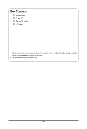
... a motherboard, CPU or memory. If you do not have an ESD wrist strap, keep your hands dry and first touch a metal object to eliminate static electricity. • Prior to installing the motherboard, please have it on top of an antistatic pad or within an electrostatic shielding container. • Before unplugging the power supply cable from the motherboard, make...
Manual - Page 8
...138;Š
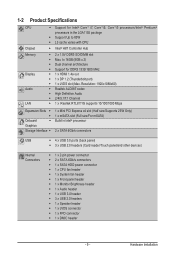
1 x Mini PCI Express x4 slot (Half size/Supports 25W Only) 1 x mSATA slot (Full size/For mSATA) Build in Intel® processor
2 x SATA 6Gb/s connectors
USB
ŠŠ 4 x USB 3.0 ports (back panel)
ŠŠ 3 x USB 2.0 headers (Card reader/Touch panel/and other devices)
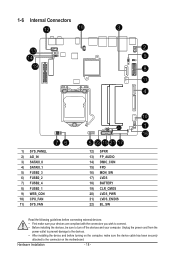
Internal Connectors
ŠŠ 1 x 2-pin power connector ŠŠ 2 x SATA 6Gb/s connectors Š...
Manual - Page 9
...
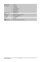
I/O Controller Hardware Monitor BIOS Form Factor
ŠŠ 1 x DC-IN ŠŠ 1 x RJ-45 port ŠŠ 1 x HDMI port ŠŠ 1 x Thunderbolt port ŠŠ 4 x USB 3.0 ports ŠŠ 1 x Audio MIC In ŠŠ 1 x Audio Line Out ŠŠ iTE IT8773 chip
ŠŠ CPU/System temperature detection ŠŠ CPU fan speed detection ŠŠ 1 x 64 Mbit flash...
Manual - Page 10
... not recommended
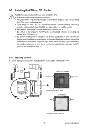
that the system bus frequency be set beyond hardware specifications since it does not meet the standard requirements for the peripherals. If you wish to set the frequency beyond the standard specifications, please do so according to your hardware specifications including the CPU, graphics card, memory, hard drive, etc.
1-3-1 Installing the CPU
A. Locate the alignment keys on...
Manual - Page 11
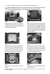
B. Follow the steps below to correctly install the CPU into the motherboard CPU socket.
Before installing the CPU, make sure to turn off the computer and unplug the power cord from the power outlet power plug to prevent any damage to prevent damage to the CPU.
Step 1: Gently press the CPU socket lever handle down and away from the socket with your finger...
Manual - Page 12
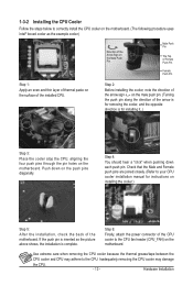
... closely. (Refer to your CPU cooler installation manual for instructions on installing the cooler.)
Step 5:
After the installation, check the back of the motherboard. If the push pin is inserted as the picture above shows, the installation is complete.
Step 6:
Finally, attach the power connector of the CPU cooler to the CPU fan header (CPU_FAN) on the motherboard.
Use extreme care when...
Manual - Page 13
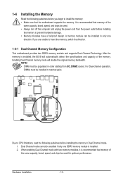
... you begin to install the memory: • Make sure that the motherboard supports the memory. It is recommended that memory of the
same capacity, brand, speed, and chips be used. • Always turn off the computer and unplug the power cord from the power outlet before installing
the memory to prevent hardware damage. • Memory modules have a foolproof design. A memory module can be...
Manual - Page 14
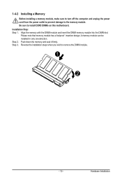
1-4-2 Installing a Memory
Before installing a memory module, make sure to turn off the computer and unplug the power cord from the power outlet to prevent damage to the memory module. Be sure to install DDR3 DIMMs on this motherboard. Installation Step: Step 1. Align the memory with the DIMM module and insert the DIMM memory module into the DIMM slot.
Please note that memory module has a foolproof...
Manual - Page 15
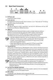
... Port The Gigabit Ethernet LAN port provides Internet connection at up to 1 Gbps data rate. The following describes the states of the LAN port LEDs.
USB 3.0 Ports The USB port supports the USB 3.0 specification. Use this port for USB devices such as a USB keyboard/mouse, USB printer, USB flash drive and etc.
HDMI Port The HDMI (High-Definition Multimedia Interface) provides an all-digital audio...
Manual - Page 16
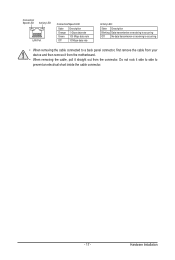
... receiving is occurring
Off
No data transmission or receiving is occurring
• When removing the cable connected to a back panel connector, first remove the cable from your device and then remove it from the motherboard.
• When removing the cable, pull it straight out from the connector. Do not rock it side to side to...
Manual - Page 17
... the connectors you wish to connect. • Before installing the devices, be sure to turn off the devices and your computer. Unplug the power cord from the
power outlet to prevent damage to the devices. • After installing the device and before turning on the computer, make sure the device cable has been securely
attached to the connector on the motherboard.
Hardware Installation
- 18 -
Manual - Page 18
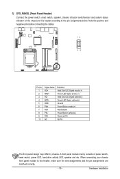
...- RSV NC
Definition Hard Disk LED Signal anode (+) Power LED Signal anode (+) Hard Disk LED Signal cathode(-) Power LED Signal cathode(-) Ground Power Button anode (+) Reset Button Power Button cathode(-) Reserved Pin No Pin
The front panel design may differ by chassis. A front panel module mainly consists of power switch, reset switch, power LED, hard drive activity LED, speaker...
Manual - Page 19
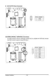
...AD_IN (2 Pin Power Connector)
1
Pin No. Definition 1 GND 2 +19V
2
DEBUG PORT
3/4) SATAIII_0/SATAIII_1 (SATA 6Gb/s Connectors) The SATA connectors conform to SATA 6Gb/s standard and are compatible with SATA 3Gb/s standard. Each SATA connector supports a single SATA device.
SATAIII_0 SATAIII_1
7
Pin No. Definition
1 GND
2 TXP
3 TXN
4 GND
1
5 RXN
6 RXP
7 GND
Hardware Installation
- 20...
Manual - Page 20
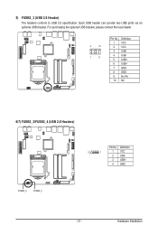
.... Each USB header can provide two USB ports via an optional USB bracket. For purchasing the optional USB bracket, please contact the local dealer.
2
10
1
9
Pin No. 1 2 3 4 5 6 7 8 9 10
Definition VCC VCC USBUSBUSB+ USB+ GND GND No Pin NC
6/7) FUSB2_3/FUSB2_4 (USB 2.0 Headers)
Pin No. Definition
5
1
1 VCC
2 USB-
3 USB+
4 GND
FUSB2_4
FUSB2_2
- 21 -
Hardware Installation
Manual - Page 21
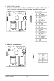
... 3.0 Header) The headers conform to USB 3.0 specification. Each USB header can provide two USB ports via an optional USB bracket. For purchasing the optional USB bracket, please contact the local dealer.
Pin No. Definition
1 Power
1011
2 IntA_P1_SSRX-
3 IntA_P1_SSRX+
4 GND
5 IntA_P1_SSTX-
6 IntA_P1_SSTX+
1 20
7 GND
8 IntA_P1_D-
9 IntA_P1_D+
10 OC
11 IntA_P2_D+
12 IntA_P2_D-
13 GND...
Manual - Page 22
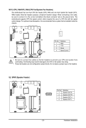
... the ground wire). The motherboard supports CPU fan speed control, which requires the use of a CPU fan with fan speed control design. For optimum heat dissipation, it is recommended that a system fan be installed inside the chassis.
1
SYS_FAN CPU_FAN
Pin No. 1 2 3 4
Definition GND +12V Sense Speed Control
• Be sure to connect fan cables to the fan headers to...
Manual - Page 23
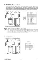
... connection between the module connector and the motherboard header will make the device unable to work or even damage it.
9
1
10
2
Pin No. 1 2 3 4 5 6 7 8 9 10
Definition F_MIC_L GND F_MIC_R GPIO_DET F_LINE_R F_MIC_JD GND No Pin F_LINE_L F_LINE_JD
• The front panel audio header supports HD audio by default. • Audio signals will be present on both of...
Manual - Page 43
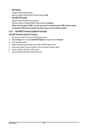
... enter the BIOS setup screen. 2. Select Chipset menu, select Intel ME FW Update and set this item to Enabled. 3. Save and reset system. 4. System rebooting automatically, and re-enter the BIOS setup screen. 5. Press power button to power off system. (Do not plug-off the power cable) 6. Power on system and boot to DOS screen. 7. Using Intel flash tool to flash Intel ME firmware.
BIOS Setup
- 44...