Gigabyte MZBAYAI driver and firmware
Related Gigabyte MZBAYAI Manual Pages
Download the free PDF manual for Gigabyte MZBAYAI and other Gigabyte manuals at ManualOwl.com
Manual - Page 3
... 10
1-3-1 Installing a Memory 10 1-4 Back Panel Connectors 11 1-5 Internal Connectors 12
Chapter 2 BIOS Setup 24 2-1 The Main Menu 26 2-2 Advanced Menu 28
2-2-1 Super IO Configuration 29 2-2-1-1 Serial Port Configuration 30 2-2-1-2 Parallel Port Configuration 31 2-2-2 Hardware Monitor 32 2-2-3 S5 RTC Wake Settings 33 2-2-4 CPU Configuration 34 2-2-4-1 CPU Information...35 2-2-5 SATA...
Manual - Page 4
Box Contents
Motherboard Driver DVD One SATA power cable Two I/O Shield (Standard 44.45mm/Low-Profile 25.54mm) Three Screws
• The box contents above are for reference only and the actual items shall depend on the product package you obtain. The box contents are subject to change without notice.
• The motherboard image is for reference only.
- 4 -
Manual - Page 7
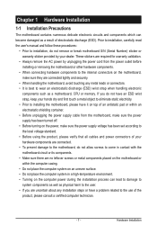
... a motherboard, CPU or memory. If you do not have an ESD wrist strap, keep your hands dry and first touch a metal object to eliminate static electricity. • Prior to installing the motherboard, please have it on top of an antistatic pad or within an electrostatic shielding container. • Before unplugging the power supply cable from the motherboard, make...
Manual - Page 8
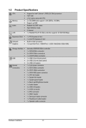
... power connector 1 x SATA 6Gb/s connector 2 x SATA 3Gb/s connectors 1 x SATA HDD power connector 1 x CPU fan header 1 x System fan header 1 x System panel header 1 x Back Light Brightness header 1 x Audio header 3 x USB 2.0 headers 1 x LVDS connector 1 x FPD connector 1 x DMIC header 1 x Serial port cable connector 1 x Parallel port cable header 1 x Speaker cable connector
Hardware Installation...
Manual - Page 9
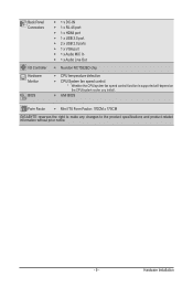
... HDMI port ŠŠ 1 x USB 3.0 port ŠŠ 2 x USB 2.0 ports ŠŠ 1 x VGA port ŠŠ 1 x Audio MIC In ŠŠ 1 x Audio Line Out
ŠŠ Nuvoton NCT5526D chip
ŠŠ CPU temperature detection ŠŠ CPU/System fan speed control * Whether the CPU/system fan speed control function is supported will depend on
the CPU/system cooler you install. Š...
Manual - Page 10
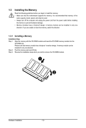
... you begin to install the memory: • Make sure that the motherboard supports the memory. It is recommended that memory of the
same capacity, brand, speed, and chips be used. • Always turn off the computer and unplug the power cord from the power outlet before installing
the memory to prevent hardware damage. • Memory modules have a foolproof design. A memory module can be...
Manual - Page 11
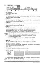
... Power Jack Connect the DC power to this port.
RJ-45 LAN Port The Gigabit Ethernet LAN port provides Internet connection at up to 1 Gbps data rate. The following describes the states of the LAN port LEDs.
USB 3.0 Port The USB port supports the USB 3.0 specification. Use this port for USB devices such as a USB keyboard/mouse, USB printer, USB flash drive and etc.
USB 2.0 Port The USB port supports...
Manual - Page 12
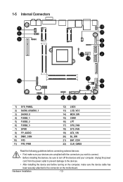
... connectors you wish to connect.
• Before installing the devices, be sure to turn off the devices and your computer. Unplug the power
cord from the power outlet to prevent damage to the devices.
• After installing the device and before turning on the computer, make sure the device cable has
been securely attached to the connector on the motherboard.
Hardware Installation
- 12 -
Manual - Page 13
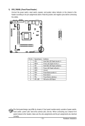
... the positive and negative pins before connecting the cables.
12
9 10
Pin No. 1 2 3 4 5 6 7 8 9
Signal Name HD+ MPD+ HDMPDGND PW+ RST PWWF_LED
Definition Hard Disk LED Signal anode (+) Power LED Signal anode (+) Hard Disk LED Signal cathode(-) Power LED Signal cathode(-) Ground Power Button anode (+) Reset Button Power Button cathode(-) Wifi active LED Signal
The front panel design may...
Manual - Page 14
...
SATAII_1 SATAII_0
1
Pin No. 1 2 3 4 5 6 7
Definition GND TXP TXN GND RXN RXP GND
DEBUG PORT
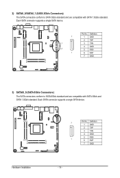
3) SATAIII_0 (SATA 6Gb/s Connectors) The SATA connectors conform to SATA 6Gb/s standard and are compatible with SATA 3Gb/s and SATA 1.5Gb/s standard. Each SATA connector supports a single SATA device.
Pin No. Definition 7
1 GND
2 TXP
3 TXN
4 GND
5 RXN
1
6 RXP
7 GND
Hardware Installation
- 14 -
Manual - Page 15
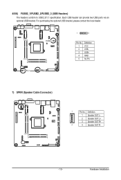
.... Each USB header can provide two USB ports via an optional USB bracket. For purchasing the optional USB bracket, please contact the local dealer.
FUSB2_3
FUSB2_2
FUSB2_1
1
5
Pin No. 1 2 3 4 5
Definition VCC USBUSB+ GND No Pin
7) SPKR (Speaker Cable Connector)
1
Pin No. Definition
1 Speaker OUT L-
2 Speaker OUT L+
3 Speaker OUT R+
4
4 Speaker OUT R-
- 15 -
Hardware Installation
Manual - Page 16
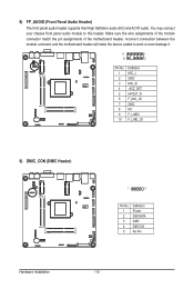
... front panel audio header supports Intel High Definition audio (HD) and AC'97 audio. You may connect your chassis front panel audio module to this header. Make sure the wire assignments of the module connector match the pin assignments of the motherboard header. Incorrect connection between the module connector and the motherboard header will make the device unable...
Manual - Page 17
...)
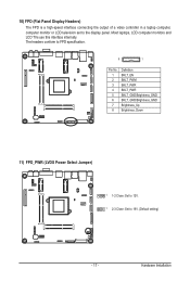
The FPD is a high-speed interface connecting the output of a video controller in a laptop computer, computer monitor or LCD television set to the display panel. Most laptops, LCD computer monitors and LCD TVs use this interface internally. The headers conform to FPD specification.
8
1
Pin No. 1 2 3 4 5 6 7 8
Definition BKLT_EN BKLT_PWM BKLT_PWR BKLT_PWR BKLT_GND/Brightness_GND BKLT_GND...
Manual - Page 18
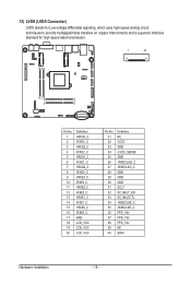
... 38 39 40
Definition NC VCC3 GND -LVDS_SENSE GND +RXECLKO_C -RXECLKO_C GND GND GND SCL1 SC_BKLT_EN SC_BKLTCTL +RXECLKE_C -RXECLKE_C FPD_19V FPD_19V FPD_19V NC SDA1
Hardware Installation
- 18 -
Manual - Page 19
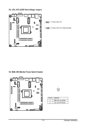
13) LCD_VCC (LVDS Drive Voltage Jumper)
1
1-2 Close: Set to 3V.
1
2-3 Close: Set to 5V. (Default setting)
14) MON_SW (Monitor Power Switch Header)
1 2
Pin No. 1 2
Definition High: turn on monitor Low: turn off monitor
- 19 -
Hardware Installation
Manual - Page 21
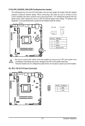
... ground wire). The motherboard supports CPU fan speed control, which requires the use of a CPU fan with fan speed control design. For optimum heat dissipation, it is recommended that a system fan be installed inside the chassis.
SYS_FAN
CPU_FAN
SYS_FAN CPU_FAN
1
1
Pin No. 1 2 3 4
Definition GND +12V Sense Speed Control
• Be sure to connect fan cables to the fan headers...
Manual - Page 22
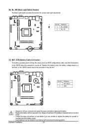
...Pin No. Definition
1 BL_DOWN
1
2 BL_UP
21) BAT_CON (Battery Cable Connector)
The battery provides power to keep the values (such as BIOS configurations, date, and time information) in the CMOS when the computer is turned off. Replace the battery when the battery voltage drops to...; Used batteries must be handled in accordance with local environmental regulations.
Hardware Installation
- 22 -
Manual - Page 23
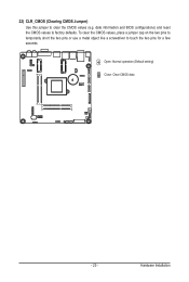
22) CLR_CMOS (Clearing CMOS Jumper) Use this jumper to clear the CMOS values (e.g. date information and BIOS configurations) and reset the CMOS values to factory defaults. To clear the CMOS values, place a jumper cap on ... or use a metal object like a screwdriver to touch the two pins for a few seconds.
Open: Normal operation (Default setting)
Close: Clear CMOS data
- 23 -
Hardware Installation
Manual - Page 27
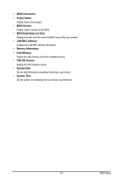
... name of the project. BIOS Version Display version number of the BIOS. BIOS Build Date and Time Displays the date and time when the BIOS setup utility was created. LAN MAC Address Displays the LAN MAC address information. Memory Information Total Memory Display the total memory size of the installed memory. TXE FW Version Display the TXE firmware version. System Date Set the date following the...
Manual - Page 32
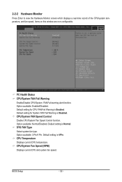
...FAN Fail Warning is Disabled. CPU/System FAN Speed Control Enable CPU/System Fan Speed Control function. Option available: Normal/Disabled. Default setting is Normal. SYS FAN Type Select system fan type. Option available: 3 Pin/4 Pin. Default setting is 4 Pin. CPU Temperature Displays current CPU temperature. CPU/System Fan Speed (RPM) Displays current CPU and system fan speed.
BIOS Setup
- 32 -