HP Chromebook 11-v000 driver and firmware
Drivers and firmware downloads for this Hewlett-Packard item
Related HP Chromebook 11-v000 Manual Pages
Download the free PDF manual for HP Chromebook 11-v000 and other HP manuals at ManualOwl.com
User Guide - Page 2
... constituting an additional warranty. HP shall not be liable for technical or editorial errors or omissions contained herein.
First Edition: July 2016
Document Part Number: 854545-001
Product notice
This guide describes features that are common to most models. Some features may not be available on your computer.
Software terms
By installing, copying, downloading, or otherwise using any...
User Guide - Page 21
... follow the on-screen instructions.
Printing with Google Cloud Print web printing service
Google Cloud Print web printing service is a free service that allows you to print documents and photos securely from your computer. For information about prerequisites and steps for using Google Cloud Print, see the HP website. 1. Go to http://support.hp.com/us-en/document...
User Guide - Page 23
... electricity from fingers or other electrostatic conductors may damage electronic components. To prevent damage to the computer, damage to a drive, or loss of information, observe these precautions: ● If removal or installation instructions direct you to unplug the computer, first be sure that it is properly
grounded. ● Keep components in their electrostatic-safe containers...
User Guide - Page 25
...audio-in) jack,
identifying 2
U USB 3.0 charging (powered) port,
identifying 1, 2
N Next window 12
P ports
HDMI 1 USB 3.0 charging (powered) 1, 2 ports; card reader 1 power button, identifying 5 power connector, identifying 1 printing 15 product name and number, computer 6
W webcam light, identifying 3 webcam, identifying 3 wireless certification label 7 WLAN antennas, identifying 3 WLAN device...
Maintenance and Service Guide - Page 7
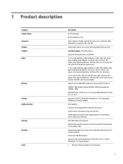
... Product Name Processor Chipset Graphics Panel
Memory
Storage Audio and video
Security Wireless
Ports
Description
HP Chromebook HP Chromebook 11 G5
Intel® Celeron® N3060 1.60 GHz (SC turbo up to 2.48 GHz) 1600 MHz/2 MB L2, Dual 6 W TDP, 4 W SDP
Integrated soldered-on-circuit (SoC) integrated with processor
Internal Graphics: Intel HD Graphics Supports HD decode, DX12, and HDMI
11.6 in...
Maintenance and Service Guide - Page 24
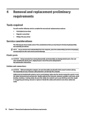
...replacement procedures: ● Flat-bladed screw driver ● Magnetic screw driver ● Phillips P0 screw driver
Service considerations
The following sections include some of ...instructions.
Cables and connectors
CAUTION: When servicing the computer, be sure that cables are placed in their proper locations during the reassembly process. Improper cable placement can damage the computer. Cables...
Maintenance and Service Guide - Page 26
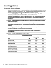
... Networks built into many integrated circuits provide some protection, but in many cases, ESD contains enough power to alter device ...computer when you are removing or installing internal components, observe these precautions:
Keep components in their electrostatic-safe containers until you are ready to install... V 12,000 V 6,000 V 2,000 V 11,500 V 14,500 V 26,500 V 21,000 V
Relative humidity 40%
15,...
Maintenance and Service Guide - Page 27
...properly grounded work surface and use properly grounded tools and equipment. ● Use conductive field service tools, such as cutters, screw drivers, and vacuums. ● When fixtures must directly contact dissipative surfaces, use fixtures made only... leads, or circuitry. ● Turn off power and input signals before inserting or removing connectors or test equipment.
Grounding guidelines 21
Maintenance and Service Guide - Page 30
... backing from the rubber feet and install them in the locations indicated in the above illustration.
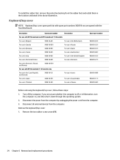
Keyboard/top cover
NOTE: Keyboard/top cover spare part kits with spare part numbers 900818-xxx are spared with the TouchPad board.
Description
Spare part number
Description
For use with HP Chromebook and HP Chromebook 11 G5 models
For use in...
Maintenance and Service Guide - Page 32
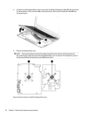
... must be thoroughly cleaned from the surfaces of the heat sink and the system board components each time the keyboard/top cover is removed. Thermal paste is used on the processor (1) and the heat sink section (2) that services it.
Reverse this procedure to install the keyboard/top cover. 26 Chapter 5 Removal and replacement procedures
Maintenance and Service Guide - Page 34
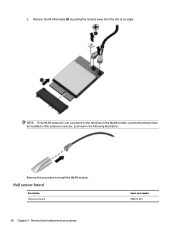
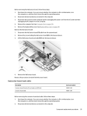
... the WLAN antenna is not connected to the terminal on the WLAN module, a protective sleeve must be installed on the antenna connector, as shown in the following illustration.
Reverse this procedure to install the WLAN module.
Hall sensor board
Description Hall sensor board
28 Chapter 5 Removal and replacement procedures
Spare part number 900815-001
Maintenance and Service Guide - Page 35
....
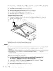
4. Remove the Hall sensor board. Reverse this procedure to install the Hall sensor board.
Connector board and cable
Description Connector board (includes SD card reader and SIM slot) Connector board cable
Spare part number 900816-001 900811-001
Before removing the connector board and cable, follow these steps: 1. Shut down the computer. If you are unsure whether the computer is off or in...
Maintenance and Service Guide - Page 36
... ZIF connector (1) to which the connector board cable is attached, and then disconnect the cable from the system board.
2. Remove the connector board and cable (2).
Reverse this procedure to install the connector board and cable.
Battery
Description
Spare part number
Battery (2-cell, 43 Wh, 3.25 AHr, Li-ion, LongLife-PL; includes cable) for use with HP Chromebook 11 G5 855710-001 models only...
Maintenance and Service Guide - Page 37
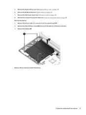
... Hall sensor board on page 28). 8. Remove the connector board and cable (see Connector board and cable on page 29). Remove the battery: 1. Release the battery cable ZIF connector from the system board (1). 2. Remove the three Phillips screws (2) that secure the battery to the base enclosure. 3. Remove the battery (3).
Reverse this procedure to install the battery.
Component replacement...
Maintenance and Service Guide - Page 38
... external devices from the computer. 4. Remove the computer feet (see Computer feet on page 23). 5. Remove the keyboard/top cover (see Keyboard/top cover on page 24). 6. Remove the WLAN module (see WLAN module on page 27). 7. Remove the Hall sensor board (see Hall sensor board on page 28). 8. Remove the connector board and cable (see Connector board and cable...
Maintenance and Service Guide - Page 40
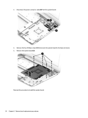
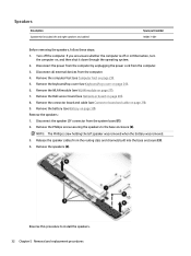
3. Disconnect the power connector cable (3) from the system board.
4. Remove the four Phillips screws (1) that secure the system board to the base enclosure. 5. Remove the system board (2).
Reverse this procedure to install the system board. 34 Chapter 5 Removal and replacement procedures
Maintenance and Service Guide - Page 42
Reverse this procedure to install the heat sink. 36 Chapter 5 Removal and replacement procedures
Maintenance and Service Guide - Page 48
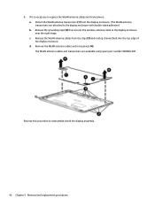
... wireless antenna cable to the display enclosure near the right hinge. c. Release the WLAN antenna cables from the clips (3) and routing channel built into the top edge of the display enclosure. d. Remove the WLAN antenna cables and transceivers (4). The WLAN antenna cables and transceivers are available using spare part number 900806-001.
Reverse this procedure to reassemble install...
Maintenance and Service Guide - Page 50
Reverse this procedure to install the power connector cable. 44 Chapter 5 Removal and replacement procedures