MSI IM945GSED driver and firmware
Related MSI IM945GSED Manual Pages
Download the free PDF manual for MSI IM945GSED and other MSI manuals at ManualOwl.com
User Guide - Page 2
...
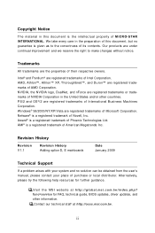
Technical Support
If a problem arises with your system and no solution can be obtained from the user's manual, please contact your place of purchase or local distributor. Alternatively, please try the following help resources for further guidance.
Visit the MSI website at http://global.msi.com.tw/index.php? func=service for FAQ, technical guide, BIOS updates, driver updates, and...
User Guide - Page 4
...
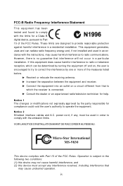
T h is eq uip men t h as been tested and found to comply with the limits for a Class B digital device, pursuant to Part 15 of the FCC Rules. These limits are designed to provide reasonable protection against harmful interference in a residential installation. This equipment generates, uses and can radiate radio frequency energy and, if not...
User Guide - Page 25
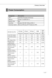
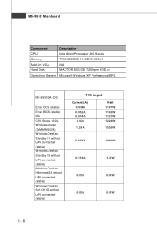
Power Consumption
Product Overview
Component CPU Memory Add-On VGA Hard Disk Operating System
Description Intel Atom Processor 200 Series Corsair 1G DDR2-800 x1 NA Western 80G IDE 7200rpm HDD x1 Microsoft Windows XP Professional SP2
MS-9830-0A (ATX)
Enter DOS (stable)
Enter BIOS (stable) Idle CPU Stress 100% Windows stress (3dMARK2006) Windows Desktop Standby S1 without LAN connected (stable) ...
User Guide - Page 26
...
Component
Description
CPU
Intel Atom Processor 200 Series
Memory
TRANSCEND 1G DDR2-800 x1
Add-On VGA
NA
Hard Disk
MAXTOR 40G IDE 7200rpm HDD x1
Operating System Microsoft Windows XP Professional SP2
MS-9830-0A (DC)
Enter DOS (stable) Enter BIOS (stable) Idle CPU Stress 100% Windows stress (3dMARK2006) Windows Desktop Standby S1 without LAN connected (stable) Windows Desktop Standby S3...
User Guide - Page 29
... chapter provides you with the information about hardware setup procedures. While doing the installation, be careful in holding the components and follow the installation procedures. For some components, if you install in the wrong orientation, the components will not work properly. Use a grounded wrist strap before handling computer components. Static electricity may damage the components...
User Guide - Page 31
... Setup
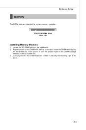
Memory
The DIMM slots are intended for system memory modules. DDR2 SO-DIMM Slot
200-pin, 1.8V
Installing Memory... Modules
1. Locate the SO-DIMM slots on the mainboard. 2. Align the notch on the DIMM with the key on the slot. Insert the DIMM vertically into
the SO-DIMM slot. Then push it in until the golden finger on the DIMM is deeply inserted in the SO-DIMM slot. 3. Manually...
User Guide - Page 39
Hardware Setup
Connector
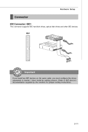
IDE Connector: IDE1
This connector supports IDE hard disk drives, optical disk drives and other IDE devices. IDE1
Important
If you install two IDE devices on the same cable, you must configure the drives separately to master / slave mode by setting jumpers. Refer to IDE device's documentation supplied by the vendors for jumper setting instructions.
2-11
User Guide - Page 48
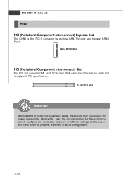
... PCI slot supports LAN card, SCSI card, USB card, and other add-on cards that comply with PCI specifications.
32-bit PCI Slot
Important
When adding or removing expansion cards, make sure that you unplug the power supply first. Meanwhile, read the documentation for the expansion card to configure any necessary hardware or software settings for the expansion card, such as jumpers, switches or BIOS...
User Guide - Page 50
....
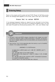
2. Upon boot-up, the 1st line appearing after the memory count is the BIOS version. It is usually in the format: A9830IMS V1.0 102708 where: 1st digit refers to BIOS maker as A = AMI, W = AWARD, and P = PHOENIX. 2nd - 5th digit refers to the model number. 6th digit refers to the chipset as I = Intel, N = nVidia, A = ATi , K=AMD and V = VIA. 7th...
User Guide - Page 53
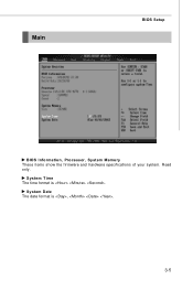
Main
BIOS Setup
BIOS Information, Processor, System Memory These items show the firmware and hardware specifications of your system. Read only.
System Time The time format is .
System Date The date format is , .
3-5
User Guide - Page 60
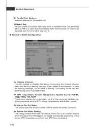
..., VCORE, 5VSB, VCC5, 12V, VBAT These items display the current status of all of the monitored hardware devices/components such as CPU voltage, temperatures and all fans' speeds.
System Fan Pin Select This setting specifies the pin numbers of the system fan power connector.
System Fan Mode Setting This setting controls the Smart Fan feature. Smart Fan is...
User Guide - Page 63
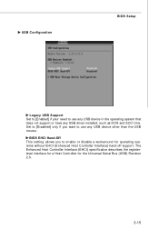
...if you want to use any USB device other than the USB mouse.
BIOS EHCI Hand-Off This setting allows you to enable or disable a workaround for operating systems without EHCI (Enhanced Host Controller Interface) hand-off support. The Enhanced Host Controller Interface (EHCI) specification describes the registerlevel interface for a Host Controller for the Universal Serial Bus (USB) Revision 2.0.
3-15
User Guide - Page 67
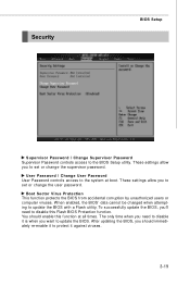
...User Password User Password controls access to the system at boot. These settings allow you to set or change the user password.
Boot Sector Virus Protection This function protects the BIOS from accidental corruption by unauthorized users or computer viruses. W hen enabled, the BIOS' data cannot be changed when attempting to update the BIOS with a Flash utility. To successfully update the BIOS, you...
User Guide - Page 76
... Mainboard
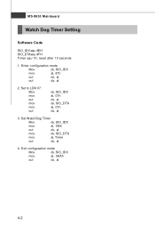
Watch Dog Timer Setting
Software Code
SIO_IDX equ 4EH SIO_DTAequ 4FH Timer equ 10; reset after 10 seconds
1. Enter configuration mode
Mov
dx, SIO_IDX
mov
al, 87h
out
dx, al
out
dx, al
2. Set to LDN 07 Mov mov...out mov mov out
dx, SIO_IDX al, 07h dx, al dx, SIO_DTA al, 07h dx, al
3. Set W atchDog Timer
Mov
dx, SIO_IDX
mov
al, 0f6h
out
dx, al
mov
dx, SIO_DTA
mov
al,...
User Guide - Page 77
System Resources
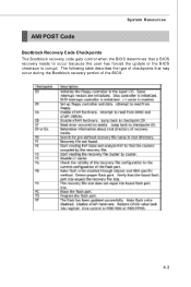
AMI POST Code
Bootblock Recovery Code Checkpoints The Bootblock recovery code gets control when the BIOS determines that a BIOS recovery needs to occur because the user has forced the update or the BIOS checksum is corrupt. The following table describes the type of checkpoints that may occur during the Bootblock recovery portion of the BIOS:
4-3