MSI IMGM45D driver and firmware
Related MSI IMGM45D Manual Pages
Download the free PDF manual for MSI IMGM45D and other MSI manuals at ManualOwl.com
User Guide - Page 2
...
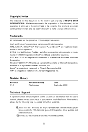
Technical Support
If a problem arises with your system and no solution can be obtained from the user's manual, please contact your place of purchase or local distributor. Alternatively, please try the following help resources for further guidance.
Visit the MSI website at http://global.msi.com.tw/index.php? func=service for FAQ, technical guide, BIOS updates, driver updates, and...
User Guide - Page 4
...
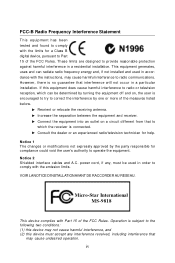
T h is eq uip men t h as been tested and found to comply with the limits for a Class B digital device, pursuant to Part 15 of the FCC Rules. These limits are designed to provide reasonable protection against harmful interference in a residential installation. This equipment generates, uses and can radiate radio frequency energy and, if not...
User Guide - Page 16
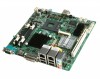
MS-9818 Mainboard
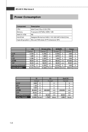
Power Consumption
Component
Description
CPU
Intel Core 2 Duo 2.2G CPU
Memory
Transcend 667MHz DDR2 1GB
Add-On VGA
NA
Hard Disk
Seagate Momentus 5400.3 160 GB SATA Hard Drive
Operating system Microsoft Windows XP Professional SP2
+3.3V +5V +12V +5VSB -12V
Power line @115VoltsAC
TOTAL POWER
Idle Current
0.700 A 1.540 A 0.390 A 56.00 mA 42.00 mA 0.170 A 15...
User Guide - Page 19
... chapter provides you with the information about hardware setup procedures. While doing the installation, be careful in holding the components and follow the installation procedures. For some components, if you install in the wrong orientation, the components will not work properly. Use a grounded wrist strap before handling computer components. Static electricity may damage the components...
User Guide - Page 21
Hardware Setup
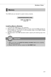
Memory
The DIMM slots are intended for system memory modules.
DDR2 SO-DIMM Slot
200-pin, 1.8V
Installing Memory Modules
1. Locate the SO-DIMM slots on... 3. Manually check if the DIMM has been locked in place by the retaining clips at the sides.
Important
1. Make sure that you install the memory modules first before installing the CPU and cooler set.
2. Always insert the memory module ...
User Guide - Page 22
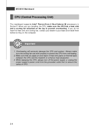
... supports Intel® Penryn/Core 2 Duo/Celeron M processors in Socket P. W hen you are installing the CPU, make sure the CPU has a heat sink and a cooling fan attached on the top to prevent overheating. If you do not have the heat sink and cooling fan, contact your dealer to purchase and install them before turning on the computer...
User Guide - Page 23
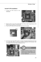
... P CPU Installation
1. Loc ate the C P U s oc ket on the mainboard.
Hardware Setup
2. Place the CPU on top of the socket. Make sure that you align the gold arrow on the CPU with the arrow key on the socket.
3. Push the CPU down until its pins securely fit into the socket.
4. On the front end of the CPU...
User Guide - Page 27
Hardware Setup
Connector
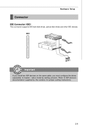
IDE Connector: IDE1
This connector supports IDE hard disk drives, optical disk drives and other IDE devices. IDE1
Important
If you install two IDE devices on the same cable, you must configure the drives separately to master / slave mode by setting jumpers. Refer to IDE device's documentation supplied by the vendors for jumper setting instructions.
2-9
User Guide - Page 35
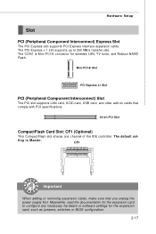
... PCI-E connector for wireless LAN, TV tuner, and Robson NAND Flash.
Mini PCI-E Slot
PCI Express x1 Slot
PCI (Peripheral Component Interconnect) Slot
The PCI slot supports LAN card, SCSI card, USB card, and other add-on cards that comply with PCI specifications.
32-bit PCI Slot
CompactFlash Card Slot: CF1 (Optional)
This CompactFlash slot shares one channel of the IDE controller. The default set...
User Guide - Page 38
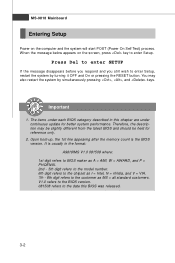
... 1st line appearing after the memory count is the BIOS version. It is usually in the format: A9818IMS V1.0 081508 where: 1st digit refers to BIOS maker as A = AMI, W = AWARD, and P = PHOENIX. 2nd - 5th digit refers to the model number. 6th digit refers to the chipset as I = Intel, N = nVidia, and V = VIA. 7th - 8th digit refers to the customer as...
User Guide - Page 41
Main
BIOS Setup
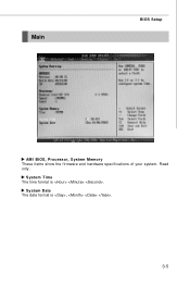
AM I BIOS, Processor, System M emory These items show the firmware and hardware specifications of your system. Read only.
System Time The time format is .
System Date The date format is , .
3-5
User Guide - Page 50
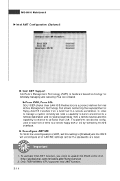
.... Unconfigure AM T/ME To finish the unconfiguration of AMT, set this setting to [Enabled] and the BIOS will unconfigure all of AMT/ME settings and all the passwords are reset.
Important
1. To activate Intel AMT function, you need to update the BIOS online first. http://global.msi.com.tw/index.php?func=service
2. Only FSB1066MHz CPU supports Intel AMT function. 3-14
User Guide - Page 54
MS-9818 Mainboard
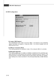
USB Configuration
Legacy USB Support Set to [Enabled] if you need to use any USB 1.1/2.0 device in the operating system that does not support or have any USB 1.1/2.0 driver installed, such as DOS and SCO Unix.
USB 2.0 Controller Mode This setting specifies the operation mode of the onboard USB 2.0 controller.
BIOS EHCI Hand-Off This setting allows you to enable or disable a ...
User Guide - Page 56
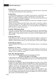
... will prevent the message from appearing on the first BIOS screen when the computer boots. Set it to [Enabled] when you want to run the BIOS Setup Utility.
Interrupt 19 Capture Interrupt 19 is the software interrupt that handles the boot disk function. W hen enabled, this BIOS feature allows the ROM BIOS of these host adaptors to "capture" Interrupt 19...
User Guide - Page 59
... performance.
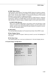
DVMT/FIXED Memory W hen set to DVMT/FIXED Mode, the graphics driver will allocate a fixed amount of memory as dedicated graphics memory, as well as allow more system memory to be dynamically allocated between the graphics processor and the operating system. PAVP M ode This setting enables/disables the Protected Audio/Video Path (PAVP) mode. Boot Display Device Use the field...
User Guide - Page 60
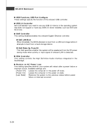
..., USB Port Configure These settings specify the function of the onboard USB controller.
USB 2.0 Controller Set to [Enabled] if you need to use any USB 2.0 device in the operating system that does not support or have any USB 2.0 driver installed, such as DOS and SCO Unix.
GbE Controller This setting disables/enables the onboard Gigabit Ethernet controller.
GbE LAN Boot W hen [Enabled], the BIOS...
User Guide - Page 64
MS-9818 Mainboard
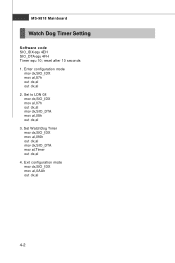
Watch Dog Timer Setting
Software code SIO_IDX equ 4EH SIO_DTA equ 4FH Timer equ 10; reset after 10 seconds 1. Enter configuration mode
mov dx,SIO_IDX mov al,87h out dx,al out dx,al 2. Set to LDN 08 mov dx,SIO_IDX ...mov al,07h out dx,al mov dx,SIO_DTA mov al,08h out dx,al 3. Set W atchDog Timer mov dx,SIO_IDX mov al,0f6h out dx,al mov dx,SIO_DTA mov al,Timer out dx...