Asus AP1710-S5 driver and firmware
Related Asus AP1710-S5 Manual Pages
Download the free PDF manual for Asus AP1710-S5 and other Asus manuals at ManualOwl.com
AP1710-S5 English Manual - Page 2
... or liability for any errors or inaccuracies that may appear in this manual, including the products and software described in it.
Product warranty or service will not be extended if: (1) the product is repaired, modified or altered, unless such repair, modification of alteration is authorized in writing by ASUS; or (2) the serial number of the product...
AP1710-S5 English Manual - Page 3
... (CPU 2-4
2.3.1 Installing the CPU 2-5 2.3.2 Installing the heatsink and fan 2-6 2.4 System memory 2-8 2.4.1 Memory configurations 2-9 2.4.2 Installing a DIMM 2-10 2.4.3 Removing a DIMM 2-10 2.5 5.25-inch drives 2-11 2.5.1 Removing the front panel assembly 2-11 2.5.2 Installing a 5.25-inch drive 2-12 2.6 Hard disk drives 2-16 2.6.1 Installing a hard disk drive 2-16 2.7 Expansion cards...
AP1710-S5 English Manual - Page 5
... for a Class B digital device, pursuant to Part 15 of the FCC Rules. These limits are designed to provide reasonable protection against harmful interference in a residential installation. This equipment generates, ...the dealer or an experienced radio/TV technician for help.
WARNING! The use of shielded cables for connection of the monitor to the graphics card is required to assure compliance with...
AP1710-S5 English Manual - Page 6
...; Before installing or removing signal cables, ensure that the power cables for the system unit and all attached devices are unplugged.
• To prevent electrical shock hazard, disconnect the power cable from the electrical outlet before relocating the system.
• When adding or removing any additional devices to or from the system, ensure that the power cables for the devices are...
AP1710-S5 English Manual - Page 8
... of configuring a server.
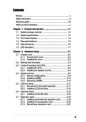
Contents
This guide contains the following parts: 1. Chapter 1: Product Introduction
This chapter describes the general features of the AP1710-S5 server. It includes sections on front panel and rear panel specifications. 2. Chapter 2: Hardware setup This chapter lists the hardware setup procedures that you have to perform when installing or removing system components...
AP1710-S5 English Manual - Page 9
...1. ASUS PRL-DL Motherboard User Manual
This manual contains detailed information about the PRL-DL motherboard. 2. ASUS Websites The ASUS websites worldwide provide updated information on ASUS hardware and software products. The ASUS websites are listed in the
ASUS contact information on page x. 3. Optional Documentation
Your product package may include optional documentations such as CD-ROM manual...
AP1710-S5 English Manual - Page 12
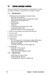
...board • CD-ROM drive • floppy disk drive • chassis fan • hot-swap SCSI hard disk drive trays (6 units) • chassis roller wheels (4 sets) • special CPU heatsink and fan assembly (2 sets)
2. ASUS PXL-S30 Ultra320 dual-channel SCSI RAID card
3. AC power cable 4. System screws and labels 5. Keys (2 pieces) 6. Support CDs
• AP1710-S5 support CD including drivers...
AP1710-S5 English Manual - Page 14
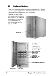
... AP1710-S5 chassis displays a stylish front bezel with lock. The bezel covers the system components on the front panel and serves as security. Open the bezel to access the front panel components. The power and reset buttons, LED indicators, CD-ROM drive, floppy drive, and two USB ports are located on the front panel. For future installation of 5.25-inch devices...
AP1710-S5 English Manual - Page 17
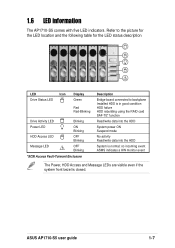
... status description
!
LED
Icon
Drive Status LED
Display Green
Red Red-Blinking
Drive Activity LED
Blinking
Power LED
HDD Access LED
Message LED
!
ON Blinking
OFF Blinking
OFF Blinking
*SCSI Access Fault-Tolerant Enclosure
Description
Bridge board connected to backplane Installed HDD is in good condition HDD failure HDD rebuilding using the RAID card SAF-TE* function
Read/write...
AP1710-S5 English Manual - Page 19
Chapter 2
This chapter lists the hardware setup procedures that you have to perform when installing or removing system components.
Hardware setup
ASUS AP1710-S5 user guide
2-1
AP1710-S5 English Manual - Page 20
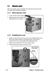
... head screw drivers that you might need to facilitate installation.
2.1.1 Removing the cover
1. Loosen the two thumb screws that secure the side cover. 2. Slide the side cover for about half an inch toward the rear until it is
disengaged from the chassis.
1
2
2.1.2 Installing the cover
...secure the cover.
Hole on the side of the chassis
1
Hook on the cover
3 2
2-2
Chapter 2: Hardware setup
AP1710-S5 English Manual - Page 21
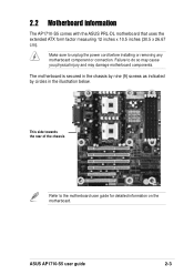
2.2 Motherboard information
The AP1710-S5 comes with the ASUS PRL-DL motherboard that uses the extended ATX form factor measuring 12 inches x 10.5 inches (30.5 x 26.67 cm).
Make sure to unplug the power cord before installing or removing any motherboard component or connection. Failure to do so may cause you physical injury and may damage motherboard components.
The motherboard is...
AP1710-S5 English Manual - Page 22
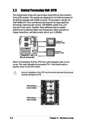
... 533Mhz FSB
Note in the illustration that the CPU has a gold triangular mark on one corner. This mark indicates the processor Pin 1 that should match a specific corner of the CPU socket.
Incorrect installation of the CPU into the socket may bend the pins and severely damage the CPU!
CPU Socket 2 (outer socket)
CPU Socket 1 (inner socket)
2-4
Chapter 2: Hardware setup
AP1710-S5 English Manual - Page 23
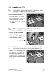
.... DO NOT force the CPU into the socket to prevent bending the pins and damaging the CPU!
4. When the CPU is in place, press it firmly on the socket while you push down the socket lever to secure the CPU. The lever clicks on the side tab to indicate that it is locked.
ASUS AP1710-S5 user guide
2-5
AP1710-S5 English Manual - Page 24
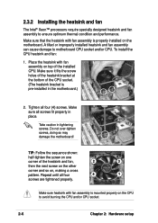
... Intel® Xeon™ processors require specially designed heatsink and fan assembly to ensure optimum thermal condition and performance.
Make sure that the heatsink with fan assembly is properly installed on the motherboard. A tilted or improperly installed heatsink and fan assembly can cause damage to motherboard CPU socket and/or CPU. To install the CPU heatsink and fan:
1. Place...
AP1710-S5 English Manual - Page 25
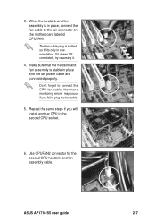
... is stable in place and the fan power cable are connected properly.
Don't forget to connect the CPU fan cable. Hardware monitoring errors may occur if you fail to plug the fan cable.
5. Repeat the same steps if you will install another CPU in the second CPU socket.
6. Use CPUFAN2 connector for the second CPU heatsink and fan assembly cable.
ASUS AP1710-S5 user guide
2-7
AP1710-S5 English Manual - Page 26
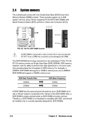
...memory
The motherboard comes with four Double Data Rate (DDR) Dual Inline Memory Module (DIMM) sockets. These sockets support up to 4GB system memory using 184-pin registered PC2100/PC1600 DIMMs with Serial Presence Detect (SPD) and Error...throughput of SDR memory. For example, a 200MHz DDR DIMM will support a 100MHz memory bus, and a 266MHz DDR DIMM will support a 133MHz memory bus.
DDR Data ...
AP1710-S5 English Manual - Page 28
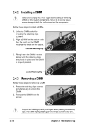
...unplug the power supply before adding or removing DIMMs or other system components. Failure to do so may cause severe damage to both the motherboard and the components.
Follow these steps to install a ... clips outward
simultaneously to unlock the DIMM. 2. Remove the DIMM from the socket.
2-10
Support the DIMM lightly with your fingers when pressing the retaining clips. The DIMM might get damaged ...
AP1710-S5 English Manual - Page 29
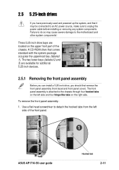
...power source, make sure to unplug the power cable before installing or removing any system components. Failure to do so may cause severe damage to the motherboard and other system components!
Three 5.25-inch drive bays are
located on the upper front part of the
chassis. A CD-ROM drive... to detach the hooked tabs from the left side of the front panel.
1
ASUS AP1710-S5 user guide
Hooked tab
2-11
AP1710-S5 English Manual - Page 53
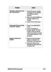
... is active.
2. Check if the HDDs are properly installed. On SCSI models, make sure that the cables are properly connected to the SCSI connectors on the backplane.
Network connection not available
1. Make sure that the network cable is connected to the RJ-45 port on the rear panel.
2. Make sure that you have installed the LAN drivers from the support CD.
ASUS AP1710-S5 user guide
A-3