Asus AP140R driver and firmware

Related Asus AP140R Manual Pages
Download the free PDF manual for Asus AP140R and other Asus manuals at ManualOwl.com
AP140R User Manual English Edition - Page 2
... are released for each product design represented by the digit before and after the period of the manual revision number. Manual updates are represented by the third digit in the manual revision number. For previous or updated manuals, BIOS, drivers, or product release information, contact ASUS at http://www.asus.com.tw or through any of the means indicated on the following...
AP140R User Manual English Edition - Page 3
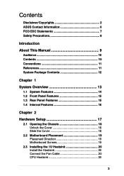
... 13
1.1 System Features 14 1.2 Front Panel Features 15 1.3 Rear Panel Features 15 1.4 Internal Features 16
Chapter 2
Hardware Setup 17
2.1 Opening the Chassis 18 Unlock the Cover 18 Slide the Cover 18
2.2 Motherboard Placement 19 Placement Direction 19 Motherboard Screws 19
2.3 Installing the 1U Heatsink 20 Install the Heatsink 20 Connect the Fan Cable 20 CPU Heatsink 20
3
AP140R User Manual English Edition - Page 4
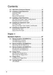
... Power Cable Configurations 23 Motherboard IDE Connectors 23 2.6 Installing an Expansion Card 25 PCI Riser Card 25 Remove the Riser Card, Holder, and Bracket 25 2.6 Installing an Expansion Card 26 Install the PCI Card 26 Secure the PCI Card 26
Chapter 3
Hardware Options 27
3.1 Remove/Install a CD-ROM Drive 28 CD-ROM Drive Location 28 CD-ROM Adapter Board 28
3.1 Remove/Install a CD-ROM...
AP140R User Manual English Edition - Page 7
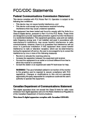
... for a Class B digital device, pursuant to Part 15 of the FCC Rules. These limits are designed to provide reasonable protection against harmful interference in a residential installation. This equipment generates, ...the dealer or an experienced radio/TV technician for help.
WARNING! The use of shielded cables for connection of the monitor to the graphics card is required to assure compliance with...
AP140R User Manual English Edition - Page 8
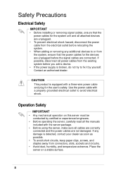
...; Before installing or removing signal cables, ensure that the power cables for the system unit and all attached devices are unplugged.
• To prevent electrical shock hazard, disconnect the power cable from the electrical outlet before relocating the system.
• When adding or removing any additional devices to or from the system, ensure that the power cables for the devices are...
AP140R User Manual English Edition - Page 10
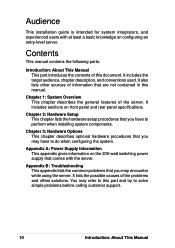
... information that are not contained in this manual.
Chapter 1: System Overview This chapter describes the general features of the server. It includes sections on front panel and rear panel specifications.
Chapter 2: Hardware Setup This chapter lists the hardware setup procedures that you have to perform when installing system components.
Chapter 3: Hardware Options This chapter...
AP140R User Manual English Edition - Page 11
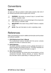
... sources for additional information and for product and software updates.
1. ASUS Motherboard User's Manual The motherboard manual included with this server contains detailed information for advanced users.
2. ASUS Websites The ASUS websites worldwide provide updated information on ASUS hardware and software products. The ASUS websites are listed in the ASUS Contact Information on page 6.
3. Other...
AP140R User Manual English Edition - Page 12
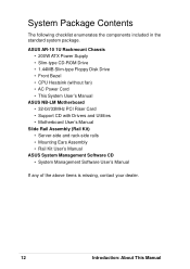
... Chassis • 200W ATX Power Supply • Slim-type CD-ROM Drive • 1.44MB Slim-type Floppy Disk Drive • Front Bezel • CPU Heatsink (without fan) • AC Power Cord • This System User's Manual
ASUS NB-LM Motherboard • 32-bit/33MHz PCI Riser Card • Support CD with Drivers and Utilities • Motherboard User's Manual
Slide Rail Assembly (Rail Kit...
AP140R User Manual English Edition - Page 17
Chapter 2
This chapter describes the hardware setup procedures that you have to perform when installing system components.
Hardware Setup
AP140R Server User's Manual
17
AP140R User Manual English Edition - Page 18
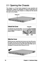
2.1 Opening the Chassis
The chassis is a 1U form factor designed for easy assembly and disassembly, making the installation of internal components very convenient. At the top of the chassis is a rotating lock that secures the cover to the chassis.
Rotating Lock
... to the inner side of the back panel. Make sure to disengage the locking tabs before lifting up the cover.
18
Chapter 2: Hardware Setup
AP140R User Manual English Edition - Page 19
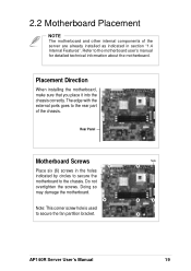
... other internal components of the server are already installed as indicated in section "1.4 Internal Features". Refer to the motherboard user's manual for detailed technical information about the motherboard.
Placement Direction
When installing the motherboard, make sure that you place it into the chassis correctly. The edge with the external ports goes to the rear part of the...
AP140R User Manual English Edition - Page 20
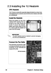
... screw a little at a time in a circle so that the heatsink will rest on the CPU evenly.
IMPORTANT
The CPU heatsink must be installed to prevent damaging the CPU and motherboard.
Connect the Fan Cable
From the factory, the CPU fan cable is already connected to the 3-pin fan connector on the motherboard marked CPU_FAN.
CPU Fan Connector
20
Chapter 2: Hardware Setup
AP140R User Manual English Edition - Page 22
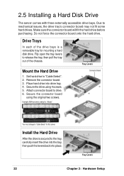
... Drive
1. Set hard drive to "Cable Select". 2. Remove the connector board. 3. Place hard drive into drive tray. 4. Secure the drive using 4 screws. 5. Attach connector board to drive. 6. Secure the connector board
using the original two screws.
Example: IBM hard drive's default is "Master".
Connector Board
You must change to "Cable Select" for this server.
Install the Hard Drive
After the drive...
AP140R User Manual English Edition - Page 23
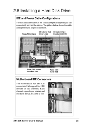
...proper connections.
IDE Cable for Hard IDE Cable for Hard
Floppy Ribbon Cable Drives 1 and 2
Drive 0 and CD-ROM
Power Cable for Hard Drive Back Plane
Power Cable for CD-ROM
Motherboard IDE Connectors
The motherboard has two IDE connectors that support four IDE devices on two channels. Each channel supports one master and one slave device, for a total of four.
AP140R Server User's Manual
23
AP140R User Manual English Edition - Page 25
...
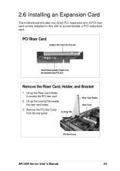
Install a PCI card into this slot
Install these golden fingers into the motherboard PCI slot
Remove the Riser Card, Holder, and Bracket
1. Lift up the Riser Card Holder to access the PCI riser card.
2. Lift up the Locking Tab beside the riser card holder.
3. Remove the PCI Slot Cover
from the rear panel.
Locking Tab
Riser Card Holder Riser Card
PCI Slot Cover
AP140R Server User's Manual...
AP140R User Manual English Edition - Page 26
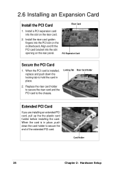
... Card
Install the PCI Card
Riser Card
1. Install a PCI expansion card into the slot on the riser card.
2. Install the riser card golden fingers into the PCI slot on the motherboard. Align and fit the PCI card bracket into the slot opening on the rear panel.
PCI Expansion Card
Secure the PCI Card
1. When the PCI card is installed, replace and push down the locking tab to hold the card...
AP140R User Manual English Edition - Page 28
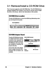
... supports a slim CD-ROM drive. The CD-ROM drive is already installed in the chassis. If you have to remove and re-install the drive in the future, refer to the instructions in this section.
CD-ROM Drive Location
The slim CD-ROM drive is on top of the HDD0 bay (leftmost bay when you are facing the front panel).
Slim CD-ROM Drive
CD-ROM Adapter Board...
AP140R User Manual English Edition - Page 29
3.1 Remove/Install a CD-ROM Drive
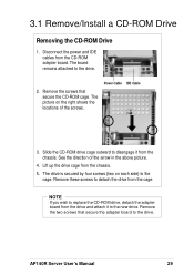
Removing the CD-ROM Drive
1. Disconnect the power and IDE cables from the CD-ROM adapter board. The board remains attached to the drive.
2. Remove the screws that secure the CD-ROM cage. The picture on the right shows the locations of the screws.
Power Cable IDE Cable
3. Slide the CD-ROM drive cage outward to disengage it from the chassis. See the direction...
AP140R User Manual English Edition - Page 30
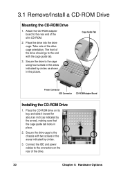
... CD-ROM Adapter Board
Installing the CD-ROM Drive
1. Place the CD-ROM drive on its bay and slide it inward for about an inch (as indicated by the arrow), making sure that the cage guide tab locks in place.
2. Secure the drive cage to the chassis with two screws in the areas indicated by circles.
3. Connect the IDE and power cables...
AP140R User Manual English Edition - Page 43
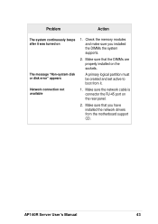
... you installed the DIMMs the system supports.
2. Make sure that the DIMMs are properly installed on the sockets.
A primary logical partition must be created and set active to boot from it.
1. Make sure the network cable is connector the RJ-45 port on the rear panel.
2. Make sure that you have installed the network drivers from the motherboard support CD.
AP140R Server User's Manual...