Asus Terminator P-III driver and firmware

Related Asus Terminator P-III Manual Pages
Download the free PDF manual for Asus Terminator P-III and other Asus manuals at ManualOwl.com
E787 MANUAL TERMINATOR English - Page 2
... WITHOUT NOTICE, AND SHOULD NOT BE CONSTRUED AS A COMMITMENT BY ASUS. ASUS ASSUMES NO RESPONSIBILITY OR LIABILITY FOR ANY ERRORS OR INACCURACIES THAT MAY APPEAR IN THIS MANUAL, INCLUDING THE PRODUCTS AND SOFTWARE DESCRIBED IN IT. Copyright © 2001 ASUSTeK COMPUTER INC. All Rights Reserved.
Product Name: Terminator Barebone System Manual Revision: 1.01 E787 Release Date: May 2001
2
E787 MANUAL TERMINATOR English - Page 4
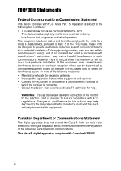
... for a Class B digital device, pursuant to Part 15 of the FCC Rules. These limits are designed to provide reasonable protection against harmful interference in a residential installation. This equipment generates, ...the dealer or an experienced radio/TV technician for help.
WARNING! The use of shielded cables for connection of the monitor to the graphics card is required to assure compliance with...
E787 MANUAL TERMINATOR English - Page 5
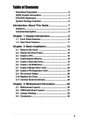
... Detach the Drive Frame 15 2.3 Install a CPU 16 2.4 Install System Memory 18 2.5 Install a Hard Disk Drive 19 2.6 Install a CD-ROM Drive 21 2.7 Install a Modem Riser Card 23 2.8 Install a PCI Expansion Card 24 2.9 Re-connect Cables 25 2.10 Replace the Cover 26 2.11 Connect External Devices 28
Chapter 3: Motherboard Information 29
3.1 Motherboard Layout 30 3.2 USB/Audio Board Layout 31...
E787 MANUAL TERMINATOR English - Page 6
...Contents
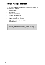
The following checklist enumerates the components included in the standard system package. 1) System Chassis 2) Motherboard 3) Switching Power Supply 4) 1.44MB Floppy Disk Drive 5) CD-ROM Drive (optional) 6) 56K PCI Modem Card (optional) 7) Support CD with Drivers and Utilities 8) Installation Guide
NOTE If you are assembling the system by yourself, make sure to prepare all the components...
E787 MANUAL TERMINATOR English - Page 7
Introduction
You are reading the ASUS Terminator Barebone System Installation Guide. This guide provides general information and installation instructions about the Terminator Barebone System. "About This Guide" contains an introduction on the contents of this document that include target audience and chapter description.
About This Guide
ASUS Terminator Barebone System
7
E787 MANUAL TERMINATOR English - Page 8
... how to install components into the barebone system through illustrated step-by-step instructions.
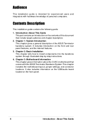
4. Chapter 3: Motherboard Information This chapter gives information about the CUSC motherboard that comes with the ASUS Terminator Barebone System.This chapter includes the motherboard layout, jumper settings, and connector locations. It also includes information on the USB/audio board located on...
E787 MANUAL TERMINATOR English - Page 10
...
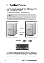
The ASUS Terminator barebone system is composed of the ASUS CUSC motherboard, a power supply, and a floppy disk drive in the ASUS TriOptix form factor chassis. The following figures show the front panel features.
NOTE The CD-ROM drive and modem card are optional items and may not come installed in some models.
CD-ROM Drive (optional)
Floppy Drive
Power Button Power LED HDD LED
USB Connectors...
E787 MANUAL TERMINATOR English - Page 12
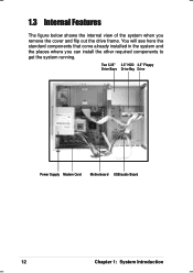
... system when you remove the cover and flip out the drive frame. You will see here the standard components that come already installed in the system and the places where you can install the other required components to get the system running.
Two 5.25" 3.5" HDD 3.5" Floppy Drive Bays Drive Bay Drive
Power Supply Modem Card Motherboard USB/audio Board
12
Chapter 1: System Introduction
E787 MANUAL TERMINATOR English - Page 13
Chapter 2
This chapter tells how to install components into the barebone system through illustrated step-by-step instructions.
Basic Installation
ASUS Terminator Barebone System
13
E787 MANUAL TERMINATOR English - Page 14
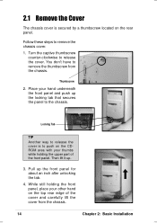
... front panel, place your other hand on the top rear edge of the cover and carefully lift the cover from the chassis.
14
Chapter 2: Basic Installation
E787 MANUAL TERMINATOR English - Page 15
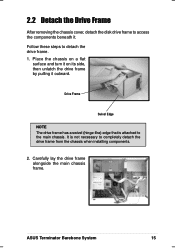
... unlatch the drive frame by pulling it outward.
Drive Frame
Swivel Edge
NOTE The drive frame has a swivel (hinge-like) edge that is attached to the main chassis. It is not necessary to completely detach the drive frame from the chassis when installing components.
2. Carefully lay the drive frame alongside the main chassis frame.
ASUS Terminator Barebone System...
E787 MANUAL TERMINATOR English - Page 16
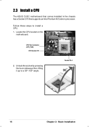
2.3 Install a CPU
The ASUS CUSC motherboard that comes installed in the chassis has a Socket 370 that supports an Intel Pentium III/Celeron processor.
Follow these steps to install a CPU. 1. Locate the CPU socket on the
motherboard.
CPU Fan Connector (CPU_FAN)
CPU Socket 370
2. Unlock the socket by pressing the lever sideways then lifting it up to a 90°-100° angle.
Socket Pin 1
16
...
E787 MANUAL TERMINATOR English - Page 17
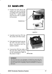
... CPU_FAN connector
on the motherboard. Refer to
the picture in step 1.
CPU Fan Cable
WARNING!
The CPU fits only in one orientation. DO NOT force the CPU into the socket to prevent bending the pins and damaging the CPU. If the CPU does not fit completely, check its orientation or check for bent pins.
ASUS Terminator Barebone System
17
E787 MANUAL TERMINATOR English - Page 18
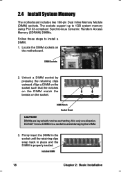
2.4 Install System Memory
The motherboard includes two 168-pin Dual Inline Memory Module (DIMM) sockets. The sockets support up to 1GB system memory using PC133-compliant Synchronous Dynamic Random Access Memory (SDRAM) DIMMs.
Follow these steps to install a DIMM. 1. Locate the DIMM sockets on
the motherboard.
DIMM Sockets
2. Unlock a DIMM socket by pressing the retaining clips outward. Align a ...
E787 MANUAL TERMINATOR English - Page 19
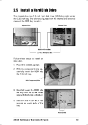
...Install a Hard Disk Drive
The chassis has one 3.5-inch hard disk drive (HDD) bay right under the 5.25-inch bay. The following figures show the internal and external views of the HDD bay location.
Internal View
External View
5.25-inch Drive Bay 3.5-inch HDD Drive Bay
Follow these steps to install... the HDD with two screws on each side of the bay.
HDD Screws
ASUS Terminator Barebone System
19
E787 MANUAL TERMINATOR English - Page 20

2.5 Install a Hard Disk Drive
5. Connect a power cable from the power supply to the power connector at the back of the HDD. Use the cable with the white connector labeled HDD.
6. Connect one end of the IDE hard disk ribbon cable to the IDE interface at the back of the HDD, matching the red stripe on the cable with Pin 1 on the IDE...
E787 MANUAL TERMINATOR English - Page 21
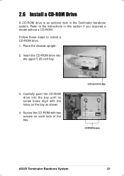
2.6 Install a CD-ROM Drive
A CD-ROM drive is an optional item in the Terminator barebone system. Refer to the instructions in this section if you acquired a model without a CD-ROM.
Follow these steps to install a CD-ROM drive. 1. Place the chassis upright.
2. Insert the CD-ROM drive into the upper 5.25-inch bay.
3. Carefully push the CD-ROM drive into the bay until its screw holes...
E787 MANUAL TERMINATOR English - Page 22
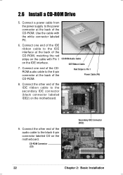
2.6 Install a CD-ROM Drive
5. Connect a power cable from the power supply to the power connector at the back of the CD-ROM. Use the cable with the white connector labeled P6.
6. Connect one end of the IDE
ribbon cable to the IDE
interface at the back of the
CD-ROM, matching the red
stripe on the cable with Pin 1 CD-ROM Audio Cable
on the IDE...
E787 MANUAL TERMINATOR English - Page 23
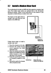
2.7 Install a Modem Riser Card
The motherboard includes an AMR slot that supports a modem riser card. The modem riser card is an optional item in the Terminator barebone system. Refer to the instructions in this section if you acquired a model without a modem riser card.
The figure on the right shows a modem riser card that you can install on the AMR slot.
Follow these steps to install a modem ...
E787 MANUAL TERMINATOR English - Page 24
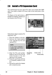
2.8 Install a PCI Expansion Card
The motherboard has two 32-bit PCI slots (one shared with AMR slot). If you wish to install a PCI card, refer to the instructions in this section.
The figure on the right shows a sample PCI network card that you can install on the PCI slot.
Follow these steps to install a PCI expansion card.
1. Place the chassis on its side. 2. Remove the metal bracket
cover...