Biostar P4TDP PRO driver and firmware

Related Biostar P4TDP PRO Manual Pages
Download the free PDF manual for Biostar P4TDP PRO and other Biostar manuals at ManualOwl.com
P4TDP Pro user's manual - Page 1
P4TDP Pro
FCC Statement and Copyright
This equipment has been tested and found to comply with the limits of a Class B digital device, pursuant to Part 15 of the FCC Rules. These limits are designed to provide reasonable protection against harmful interference in a residential installation... found in this user's manual. All the brand and product names are trademarks of their respective companies.
i
P4TDP Pro user's manual - Page 3
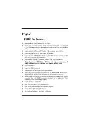
...which include two serial port, a parallel port,
a PS/2 mouse port, a PS/2 keyboard port, audio ports, USB ports, a game port . ! Supports the Intel Pentium 4® (Socket 478) processor up to 2.4GHz. ! Supports Ultra 100/66/33, BMIDE and PIO modes. ! Supports up to 2 DDR 200/ 266/ Fuzzy333 MHz devices, running at 400 MHz/ 533 Front Side Bus frequency. ! Supports five 32-bit PCI Bus slots, and one...
P4TDP Pro user's manual - Page 5
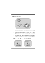
... the white dot or cut edge in the CPU. Match Pin A with the white dot/cut edge then insert the CPU.
3. Press the lever down. Then Put the fan on the CPU and buckle it and put the fan's power port into the JCFAN1, then to complete the installation.
CPU/ System Fan Headers: JCFAN1/ JSFAN1
12V Ground...
P4TDP Pro user's manual - Page 6
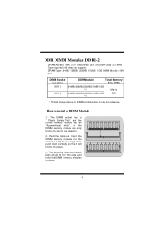
...Fuzzy 333 MHz Type required (x16 does not support). DRAM Type: 64MB/ 128MB/ 256MB/ 512MB/ 1GB DIMM Module (184 pin)
DIMM Socket Location
DDR Module
Total Memory Size (MB)
DDR 1
64MB/128MB/256MB... only for reference.
How to install a DIMM Module
1. The DIMM socket has a " Plastic Safety Tab", and the DIMM memory module has an "Asymmetrical notch", so the DIMM memory module can only fit into the...
P4TDP Pro user's manual - Page 11
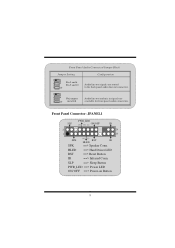
Front Panel Audio Connector/ Jumper Block
Jumper Setting
12
3 5 7
4 6
Pin 5 and 6 Pin 9 and 10
9 10
1 3 5
42 6
No jumpers
7 9
10
installed
Configuration
Audio line out signals are routed to the back panel audio line out connector.
Audio line out and mic in signals are available for front panel audio connectors.
Front Panel Connector: JPANEL1
PWR_LED
SLP
(+) (+) (-) ON/OFF
IR...
P4TDP Pro user's manual - Page 24
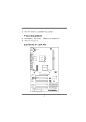
... für Installation X 1 ! USB-Kable X 2 (optional)
Layout des P4TDP Pro
JKBMS1 K/B &
Mouse
JUSB1
JKBV1 JATXPWR2
JUSBV1
JCOM1 JPRNT1
I/O
JCFAN1 1
DDR 1 DDR 2
COM1 Parallel Port
Socket 478
JCOM2 JGAME1
MIC-IN LINE-IN SP-OUT GAME Port
2
JUSB4 JUSBV4
J1
INTEL 845E
JATXPWR1 AGP1
BAT1
J D IM M V O LT 1
2 1
USB 2.0 Chip
(optional)
JAUDIO1
2 1
Codec (optional)
JCDIN1
H/W AUDIO
Chip...
P4TDP Pro user's manual - Page 34
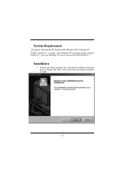
System Requirement
OS Support: Windows 98 SE, Windows Me, Windows 2000, Windows XP DirectX: DirectX 8.1 or above. (The Windows XP operating system includes DirectX 8.1. If you use Windows XP, you do not need to install DirectX 8.1.)
Installation
1. Execute the setup execution file, and then the following dialog will pop up. Please click "Next" button and follow the default procedure to install.
32
P4TDP Pro user's manual - Page 36
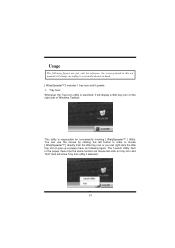
... only for reference, the screen printed in this usr manual will change according to your motherboard on hand. [ WarpSpeeder™ ] includes 1 tray icon and 5 panels: 1. Tray Icon: Whenever the Tray Icon utility is launched, it will display a little tray icon on the right side of Windows Taskbar.
This utility is responsible for conveniently invoking...
P4TDP Pro user's manual - Page 37
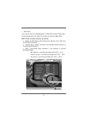
..., [ WarpSpeeder™ ] utility will be invoked. Please refer do the following figure; the utility's first window you will see is Main Panel.
Main Panel contains features as follows:
a. Display the CPU Speed, CPU external clock, Memory clock, AGP clock, and PCI clock information. b. Contains About, Voltage, Overclock, and Hardware Monitor Buttons for invoking respective panels. c. With...
P4TDP Pro user's manual - Page 44
... the
power indicator lights are lit, hard drive is DIMM, press down firmly until the module
spinning.
snaps into place.
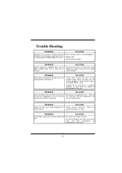
PROBABLE
SOLUTION
System does not boot from hard disk drive, can * Check cable running from disk to disk
be booted from CD-ROM drive.
controller board. Make sure both ends are
securely plugged in; check the drive type in
the standard CMOS setup...