Dell PowerEdge 2500 driver and firmware

Related Dell PowerEdge 2500 Manual Pages
Download the free PDF manual for Dell PowerEdge 2500 and other Dell manuals at ManualOwl.com
Rack-to-Tower
Conversion Guide (.pdf) - Page 3
... Front Bezel" in your Installation and
Troubleshooting Guide). 4 Remove the system cover (see "Removing the System Cover" in your Installation and
Troubleshooting Guide). NOTE: Verify that your system has the latest basic input/output system (BIOS) revision and firmware. Download the latest revision from the Dell support site at http://support.dell.com.
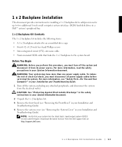
1 x 2 Backplane Kit Installation Guide
1-1
Rack-to-Tower
Conversion Guide (.pdf) - Page 4
www.dell.com | support.dell.com
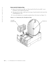
Removing the Peripheral Bay 1 Remove the front fan assembly (see "Removing the Front Fan Assembly" in your Installation and Troubleshooting Guide). 2 Disconnect the interface cable from the interposer board attached to the back of the CD-ROM/diskette drive. 3 Loosen the thumbscrew securing the peripheral bay to the chassis (see Figure 1-1).
Figure 1-1. Removing the...
Rack-to-Tower
Conversion Guide (.pdf) - Page 5
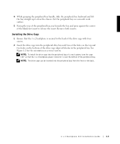
... bay straight up to clear the chassis. Set the peripheral bay on a smooth work surface.
5 Facing the rear of the peripheral bay, reach inside the bay and press against the center of the blank slot insert to release the insert. Remove both inserts.
Installing the Drive Cage 1 Ensure that the 1 x 2 backplane is secured...
Rack-to-Tower
Conversion Guide (.pdf) - Page 6
... | support.dell.com
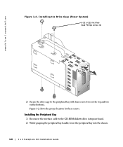
Figure 1-2. Installing the Drive Cage (Tower System)
6-32 x 0.25-inch hexhead Phillips screws (4)
3 Secure the drive cage to the peripheral bay with four screws (two on the top and two on the bottom). Figure 1-2 shows the proper location for these screws.
Installing the Peripheral Bay 1 Reconnect the interface cable to the CD-ROM/diskette drive interposer board...
Rack-to-Tower
Conversion Guide (.pdf) - Page 7
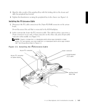
...tower system. For rack systems, you must install the 1 x 2 backplane and its drive cage oriented 180° from the position shown in Figure 1-3.
F i g u r e 1 - 3 . I n s t a l l i n g t h e I2C E x t e n s i o n C a b l e
10-pin I2C connector
power connector
20-pin I2C connector on system board
nonterminated SCSI cable
cooling shroud cable clips
1 x 2 Backplane Kit Installation Guide
1-5
Rack-to-Tower
Conversion Guide (.pdf) - Page 8
...systems and provides power to peripherals, such as a tape drive.
Installing the SCSI Cable
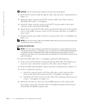
NOTE: The SCSI cable installation described in this document is a typical installation of the SCSI cable used with the 1 x 2 backplane. You can install the SCSI cable differently, depending on redundant array of independent disks (RAID) configurations and the existence of SCSI peripheral cards. Refer to your...
Rack-to-Tower
Conversion Guide (.pdf) - Page 9
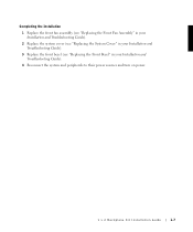
..." in your Installation and Troubleshooting Guide). 2 Replace the system cover (see "Replacing the System Cover" in your Installation and Troubleshooting Guide). 3 Replace the front bezel (see "Replacing the Front Bezel" in your Installation and Troubleshooting Guide). 4 Reconnect the system and peripherals to their power sources and turn on power.
1 x 2 Backplane Kit Installation Guide
1-7
SCSI
Backplane Daughter Card Installation (.pdf) - Page 2
... reserved. Reproduction in any manner whatsoever without the written permission of Dell Computer Corporation is strictly forbidden. Trademarks used in this text: Dell, the DELL logo, and PowerEdge are trademarks of Dell Computer Corporation; Intel is a registered trademark of Intel Corporation; Microsoft and Windows are registered trademarks of Microsoft Corporation. Other trademarks and trade...
SCSI
Backplane Daughter Card Installation (.pdf) - Page 3
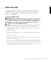
... all data on the hard-disk drives before changing the mode of operation of the integrated SCSI controller from SCSI to RAID. 1 Turn off the system, including any attached peripherals, and disconnect the AC power cable from its power source. 2 Open the front bezel. See "Removing the Front Bezel" in your system Installation and Troubleshooting Guide.
3 Remove the system cover. 4 Remove...
SCSI
Backplane Daughter Card Installation (.pdf) - Page 4
www.dell.com | support.dell.com
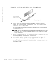
Figure 1-1. Installing the RAID Controller Memory Module
memory module socket ejectors (2)
alignment keys (2)
6 To install the memory module provided in your upgrade kit, align the memory module's edge connector with the memory module socket, and insert the memory module in the socket (see Figure 1-1).
The socket has two alignment keys that allow the memory ...
SCSI
Backplane Daughter Card Installation (.pdf) - Page 5
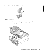
Figure 1-2. Installing the RAID Hardware Key
9 Install the RAID battery: a Hook the front edge of the RAID battery assembly into the slot near the system board, then snap the clip on the back edge of the battery assembly into place so the battery lies flat (see Figure 1-3).
Figure 1-3. Installing the RAID Battery RAID battery
Activating the Integrated RAID Controller
1-3
SCSI
Backplane Daughter Card Installation (.pdf) - Page 6
www.dell.com | support.dell.com
b Connect the battery cable to the RAID battery connector on the system board (see the system information label on the inside of the system cover for the location of this connector).
c Install the peripheral bay. See "Installing the Peripheral Bay" in the system Installation and Troubleshooting Guide.
10 Replace the cooling shroud and system cover...