Dell Precision T7600 driver and firmware
Related Dell Precision T7600 Manual Pages
Download the free PDF manual for Dell Precision T7600 and other Dell manuals at ManualOwl.com
- Page 4
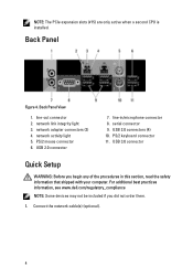
... active when a second CPU is installed.
Back Panel
Figure 4. Back Panel View
1. line-out connector 2. network link integrity light 3. network adapter connectors (2) 4. network activity light 5. PS/2 mouse connector 6. USB 2.0 connector
7. line-in/microphone connector 8. serial connector 9. USB 2.0 connectors (4) 10. PS/2 keyboard connector 11. USB 3.0 connector
Quick Setup
WARNING: Before you...
- Page 8
... is available at support.dell.com/manuals.
Information in this publication is subject to change without notice. © 2012 Dell Inc. All rights reserved. Reproduction of these materials in any manner whatsoever without the written permission of Dell Inc. is strictly forbidden. Trademarks used in this text: Dell™, the DELL logo, Dell Precision™, Precision ON™, ExpressCharge...
Owner's Manual - Page 2
... Association (BDA) and licensed for use on discs and players. The Bluetooth® word mark is a registered trademark and owned by the Bluetooth® SIG, Inc. and any use of such mark by Dell Inc. is under license. Wi-Fi® is a registered trademark of Wireless Ethernet Compatibility Alliance, Inc. 2012 - 05 Rev. A01
Owner's Manual - Page 3
... the Intrusion Switch...16 Removing the PCI Card...16 Installing the PCI Card...17 Removing the Optical Drive...17 Installing the Optical Drive...20 Removing the Air Tunnel ...20 Installing the Air Tunnel ...21 Removing the Processor/Memory Slot Cover...22 Installing the Processor/Memory Slot Cover...22 Removing the Memory...23 Installing the Memory...23 Removing the Coin-Cell Battery...23...
Owner's Manual - Page 4
... the Power Supply Unit (PSU) Card...43 Removing the System Board...44 Installing the System Board...45 System Board Components...46
3 Additional Information...49
Memory Module Guidelines...49 Front Panel Chassis Lock...49 Power Supply Unit (PSU) Lock...50
4 System Setup...51
Boot Sequence...51 Navigation Keys...51 System Setup Options...52 Updating the BIOS ...57 System and Setup Password...58...
Owner's Manual - Page 7
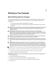
... Off Your Computer).
CAUTION: To disconnect a network cable, first unplug the cable from your computer and then unplug the cable from the network device. 3. Disconnect all network cables from the computer. 4. Disconnect your computer and all attached devices from their electrical outlets. 5. Press and hold the power button while the computer is unplugged to ground the system board. 6. Remove the...
Owner's Manual - Page 8
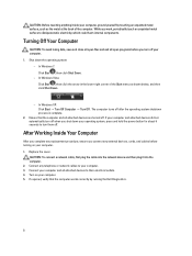
... system, press and hold the power button for about 6 seconds to turn them off.
After Working Inside Your Computer
After you complete any replacement procedure, ensure you connect any external devices, cards, and cables before turning on your computer. 1. Replace the cover.
CAUTION: To connect a network cable, first plug the cable into the network device and then plug it into the...
Owner's Manual - Page 9
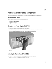
... screw to unlock the PSU. For more information, see the PSU Lock feature. 3. Press and hold the blue tab, then pull the power supply unit away from the computer.
Figure 1.
Installing the Power Supply Unit (PSU)
1. Hold the PSU handle and push the unit into its compartment until it clicks into place. 2. Follow the...
Owner's Manual - Page 11
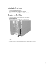
Installing the Front Cover
1. Place the front cover on the computer. 2. Press down on the front cover till it clicks into place. 3. Follow the procedures in After Working Inside Your Computer.
Removing the Hard Drive
1. Follow the procedures in Before Working Inside Your Computer. 2. Remove the front cover. 3. Pull the clasp of the hard-drive bracket in...
Owner's Manual - Page 12
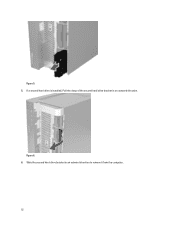
Figure 5. 5. If a second hard drive is installed, Pull the clasp of the second hard drive bracket in an outward direction.
Figure 6. 6. Slide the second hard-drive bracket in an outward direction to remove it from the computer.
12
Owner's Manual - Page 14
... from the 3.5 inch hard-drive caddy.
Figure 10.
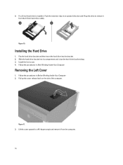
Installing the Hard Drive
1. Flex the hard drive-bracket and then insert the hard drive into the bracket. 2. Slide the hard-drive bracket into its compartment and close the hard-drive bracket clasp. 3. Install the front cover. 4. Follow the procedures in After Working Inside Your Computer.
Removing the Left Cover
1. Follow...
Owner's Manual - Page 15
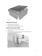
... clicks into place. 3. Follow the procedures in After Working Inside Your Computer.
Removing the Intrusion Switch
1. Follow the procedures in Before Working Inside Your Computer. 2. Remove the left cover. 3. Press the intrusion switch release latch and disconnect the connector from the system board.
a) Unroute the intrusion switch cable from the chassis.
Figure 13. 15
Owner's Manual - Page 16
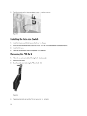
... its place holder on the chassis. 2. Route the intrusion switch cable around the chassis clips and install the connector to the system board. 3. Install the left cover. 4. Follow the procedures in After Working Inside Your Computer.
Removing the PCI Card
1. Follow the procedures in Before Working Inside Your Computer. 2. Remove the left cover. 3. Open the plastic latch fastening...
Owner's Manual - Page 17
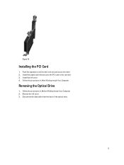
... the PCI Card
1. Push the expansion card into the card slot and secure the latch. 2. Install the plastic latch that secures the PCI card to the card slot. 3. Install the left cover. 4. Follow the procedures in After Working Inside Your Computer.
Removing the Optical Drive
1. Follow the procedures in Before Working Inside Your Computer. 2. Remove the left cover. 3. Disconnect the data cable from...
Owner's Manual - Page 20
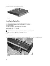
... remove it from the bracket.
Figure 22.
Installing the Optical Drive
1. Slide the optical drive into its compartment and ensure it is seated firmly. 2. Connect the power cable and the data cable to the back of the optical drive. 3. Install the left cover. 4. Follow the procedures in After Working Inside Your Computer.
Removing the Air Tunnel
NOTE: The air tunnel is an...
Owner's Manual - Page 57
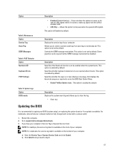
...Updating the BIOS
It is recommended to update your BIOS (system setup), on replacing the system board or if an update is available. For notebooks, ensure that your computer battery is fully charged and connected to a power outlet
1. Restart the computer. 2. Go to support.dell.com/support/downloads. 3. If you have your computer's Service Tag or Express Service Code:
NOTE: For desktops, the service...
Owner's Manual - Page 58
... method below window; click Download
Now. The File Download window appears. 8. Click Save to save the file on your computer. 9. Click Run to install the updated BIOS settings on your computer. Follow the instructions on the screen.
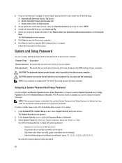
System and Setup Password
You can create a system password and a setup password to secure your computer.
Password Type Description System password Password that you...
Owner's Manual - Page 59
... disabled (erased) until the computer boots without the jumper. 5. Install the cover.
NOTE: If you assign a new system and/or setup password with the PSWD jumper installed, the system disables the new password(s) the next time it boots. 6. Connect the computer to the electrical outlet and power-on the computer. 7. Power-off the computer and disconnect the power cable from the electrical outlet...
Statement of Volatility - Page 1
... this space are lost, after several minutes, if the coin-cell battery is removed from the motherboard.
Ethernet Controller EEPROMs The Ethernet Controller EEPROM is identified as U35 on the motherboard. It is a 2 kbit device. The Ethernet Controller EEPROM stores driver information and the system MAC addresses. It does not store password, IP address, domain name, system ID, or similar information.
Statement of Volatility - Page 2
... motherboard:
The Video Card contains volatile and non-volatile memory components. The volatile frame buffer memory will lose data once power is removed. The nonvolatile memory (Video BIOS) stores only video card setup information. The video BIOS is not accessible by the user.
The CD-RW/Diskette Drives/DVD-R/W/Blu Ray DVD-R/W are input/output devices, whereas the DVD-ROM is an input device...