Gigabyte G210-H4G driver and firmware
Related Gigabyte G210-H4G Manual Pages
Download the free PDF manual for Gigabyte G210-H4G and other Gigabyte manuals at ManualOwl.com
Manual - Page 4

... Components 14 2-2 Replacing Power Supply Board Cage Cover 15 2-3 Replacing the Motherboard Tray 16 2-4 Removing and Installing the Fan Duct 17 2-5 Installing the CPU 18 2-6 Installing the Heat Sink 19 2-7 Installing the Memory 20
2-7-1 Dual Channel Memory Configuration 20 2-7-2 Installing a Memory 21 2-8 Installing the GPGPU Card 22 2-9 Installing the Hard Disk Drive 24 2-10 Replacing...
Manual - Page 5

... Configuration 40 5-2-2 Trusted Computing (Optional 41 5-2-3 PCI Subsystem Settings 42 5-2-3-1 PCI Express Settings 44 5-2-4 CPU Configuration 46 5-2-5 SATA Configuration 51 5-2-5-1 Software Feature Mask Configuration 53 5-2-6 Info Report Configuration 55 5-2-7 USB Configuration 56 5-2-8 Super IO Configuration 57 5-2-9 Serial Port Console Redirection 59 5-2-10 Network Stack...62 5-2-11...
Manual - Page 6

Box Contents
Server System Driver CD User's Manual Rail Kit 4 x Heat sinks
• The box contents above are for reference only and the actual items shall depend on the product package you obtain. The box contents are subject to change without notice.
• The motherboard image is for reference only.
- 6 -
Manual - Page 7

...; To avoid electrical shock, always unplug all power cables and modem cables from the wall outletsbefore removing covers. • Allow the product to cool before removing covers or touching internal components.
Precaution for Product with Laser Devices Observe the following precautions for laser devices: • Do not open the CD-ROM drive, make adjustments, or perform procedures on...
Manual - Page 8

... limits for a Class A digital device,pursuant to Part 15 of the FCC Rules. These limits are designed to provide reasonable protection againstharmful interference when the equipment is operated in a commercial environment. This equipmentgenerates, uses, and can radiate radio frequency energy and, if not installed and used in accordance withthe instruction manual, may cause harmful interference...
Manual - Page 9

... power utility...Load Number (LN) assigned to each terminal device denotes the...digital device pursuantPart 15 of the FCC Rules. These limits are designed to provide reasonable protection againstharmful interference when the equipment is operated in a commercial environment. This equipmentgenerate, uses, and can radiate radio frequency energy, and if not installed and used in accordancewith the instructions...
Manual - Page 10

... read the service guide and follow these procedures:
• Prior to installation, do not remove or break motherboard S/N (Serial Number) sticker or warranty sticker provided by your dealer. These stickers are required for warranty validation.
• Always remove the AC power by unplugging the power cord from the power outlet before installing or removing the motherboard or other hardware...
Manual - Page 11

... memory modules ŠŠ 2 x Intel® I210 supports 10/100/1000 Mbps
Expansion Slot ŠŠ 1 x PCIe x16 slot (Gen3 x16 bus)
ŠŠ Supports 2 x PCIe x8 slots (Gen3 x8 bus) via riser card and CFG5 jumper
Onboard
ŠŠ ASPEED AST2300 supports 128MB VRAM
Graphics
Mass Storage ŠŠ 4 x 2.5" Hot-Swap SATA HDDs
ŠŠ Support for Intel IRSTe SATA RAID...
Manual - Page 12

...138; 2 x USB 2.0 ports ŠŠ 2 x RJ-45 ports ŠŠ 1 x COM port ŠŠ 1 x VGA port ŠŠ 1 x NMI button ŠŠ 1 x Reset button ŠŠ 1 x ID Switch button/LED ŠŠ 1 x Power button/LED ŠŠ 1 x Power button/LED ŠŠ 1 x ID button/LED
BMC Controller ŠŠ ASPEED® AST2300 BMC chip
Hardware Monitor
BIOS
Environment Ambient...
Manual - Page 13

... the CPU specifications. It is not recommended
that the system bus frequency be set beyond hardware specifications since it does not meet the standard requirements for the peripherals. If you wish to set the frequency beyond the standard specifications, please do so according to your hardware specifications including the CPU, graphics card, memory, hard drive, etc.
- 13 -
Hardware Installation
Manual - Page 14

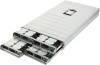
2-1 System Components 1
2
53 64 7
76
3 4 5
Item Decription 1. Power module 2. Power supply board cage 3. Fan duct 4. GPU cooling fan 5. GPGPU card
6. System fans 7. Hard drive
Hardware Installation
- 14 -
Manual - Page 15

2-2 Replacing Power Supply Board Cage Cover
Before you remove or install the power supply board cage cover • Make sure the system is not turned on or connected to AC power. Follow these instructions to remove the power supply board cage cover: 1. Loosen and remove the screw securing the cover. 2. Holding the cage and vertically lift it from the system.
1
2
Hardware Installation
- 15 -
Manual - Page 16

2-3 Replacing the Motherboard Tray
Follow these instructions to replace the motherboard tray: 1. Disconnect the power, SATA, front panel, and mainboard cable connectors. 2. Press the retaining clip on the left side of the tray along the direction of the arrow. 3. At the same time, pull out the ...
Manual - Page 17

2-4 Removing and Installing the Fan Duct
Follow these instructions to remove/install the fan duct:
1. Lift up to remove the fan duct 2. To install the fan duct, align the fan duct with the guiding groove. Push down the fan duct into
chassis until its firmly seats.
Hardware Installation
- 17 -
Manual - Page 18

... motherboard supports the CPU. • Always turn off the computer and unplug the power cord from the power outlet before installing
the CPU to prevent hardware damage. • Unplug all cables from the power outlets. • Disconnect all telecommunication cables from their ports. • Place the system unit on a flat and stable surface. • Open the system according to the instructions...
Manual - Page 33

... SATA port 4 DOM support jumper Case open intrusion header HDMI connector* Battery power cable connector SATA 6Gb/s connectors USB 2.0 header SATA SGPIO header Clear CMOS jumper ME Update jumper BIOS recovery jumper BMC readiness LED ASPEED 2300 BMC chipset IPMB connector PCI-E x16 slot TPM module connector
The HDMI connector is HDCP compliant and supports Dolby True HD and DTS HD Master Audio...
Manual - Page 38

...BMC setup utility. FRU Version Display the FRU version of the BMC setup utility. Processor Information Processor Information CPU Type/Brand String/Frequency/Processor ID/Stepping/Number of Processors/ Microcode Revison Displays the technical specifications for the installed processor. Memory Information Memory Frequency Display the frequency information of the installed memory. System Date Set the...
Manual - Page 47

... technical specifications for the installed processor. Hyper-threading The Intel Hyper Threading Technology allows a single processor to execute two or more separate threads concurrently. When hyper-threading is enabled, multi-threaded software applications can execute their threads, thereby improving performance. Options available: Enabled/Disabled. Default setting is Enabled.
BIOS Setup
- 47 -
Manual - Page 52

.... Default setting is Enabled. SATA Controller Speed
Indicates the maximum speed that the SATA controller can support. Options available: Default/Gen1/Gen2/Gen3. Default setting is Default. Software Feature Mask Configuration
Press [Enter] for configuration of advanced items. Serial Port 0/1/2/3/4/5
The category identifies Serial ATA type of hard disk that are installed in the computer. System...
Manual - Page 79

... menu
The Secure Boot Menu is applicable when your device is installed the Windows® 8 operatin system.
Platform Mode
Display the System Platform Mode State.
Secure Boot Display the status of Secure Boot. Secure Boot Control Enable/Disable Secure Boot function. Options available: Enabled/Disabled. Default setting is Disabled.
Secure Boot Mode Secure Boot requires all the...