Gigabyte MP30-AR0 driver and firmware
Related Gigabyte MP30-AR0 Manual Pages
Download the free PDF manual for Gigabyte MP30-AR0 and other Gigabyte manuals at ManualOwl.com
Manual - Page 3
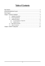
Table of Contents
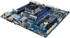
Box Contents...4 MP30-AR0 Motherboard Layout 5 Block Diagram...7 Chapter 1 Hardware Installation 8
1-1 Installation Precautions 8 1-2 Product Specifications 9 1-3 Installing the Memory 10
1-3-1 Four Channel Memory Configuration 10 1-3-2 Installing a Memory 11 1-4 Back Panel Connectors 12 1-5 Internal Connectors 14
Chapter 2 UBOOT Configuration 22
- 3 -
Manual - Page 6
... 35 DIMM_P0_D1
Description System status LED BMC Management LAN port (top)/USB 2.0 ports
(bottom) Serial port (top)/VGA port (bottom) 10G Fiber LAN ports LAN ports Power button/LED ID switch button/LED CPU fan connector Channel 1 slot 0 Channel 1 slot 1 Channel 2 slot 0 Channel 2 slot 1 ARM CPU 4 pin power connector 24 pin main power connector System fan connector#1 Front panel header (for...
Manual - Page 8
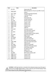
... a motherboard, CPU or memory. If you do not have an ESD wrist strap, keep your hands dry and first touch a metal object to eliminate static electricity. • Prior to installing the motherboard, please have it on top of an antistatic pad or within an electrostatic shielding container. • Before unplugging the power supply cable from the motherboard, make...
Manual - Page 9
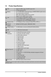
...138; Support for ARM X-Gene X3-408 Processor SoC
ŠŠ L3 cache varies with CPU
Memory
ŠŠ 8 x 1.5V DDR3 DIMM sockets supporting up to 256GB UDIMM of system memory
ŠŠ Four channel memory architecture
ŠŠ DDR3 1600/1333MHz UDIMM memory modules
ŠŠ Support for ECC UDIMM memory modules
LAN
ŠŠ 2 x XFI supports 10 Gbps SFP+ LAN ports
Š...
Manual - Page 10
...power outlet before installing
the memory to prevent hardware damage. • Memory modules have a foolproof design. A memory module can be installed in only one
direction. If you are unable to insert the memory, switch the direction.
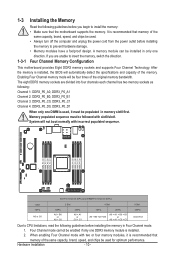
Four Channel Memory Configuration
This motherboard provides Eight DDR3 memory sockets and supports Four Channel Technology. After the memory is installed, the BIOS...
Manual - Page 11
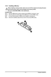
1-3-2 Installing a Memory
Before installing a memory module, make sure to turn off the computer and unplug the power cord from the power outlet to prevent damage to the memory module. Be sure to install DDR3 DIMMs on this motherboard. Installation Step: Step 1. Insert the DIMM memory module vertically into the DIMM slot, and push it down. Step 2. Close the plastic clip at both edges...
Manual - Page 12
... the following:
Off •
POST error
•
NMI error
•
Processor or terminator missing
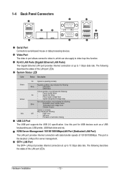
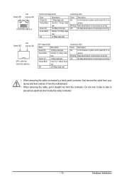
USB 2.0 Port The USB port supports the USB 2.0 specification. Use this port for USB devices such as a USB keyboard/mouse, USB printer, USB flash drive and etc. KVM Server Management 10/100/1000 MbpsLAN Port (Dedicated LAN Port)
The LAN port provides Internet connection with data transfer speeds...
Manual - Page 13
...
Link between system and network or no
access
Blinking Data transmission or receiving is occurring
Off
No data transmission or receiving is occurring
• When removing the cable connected to a back panel connector, first remove the cable from your device and then remove it from the motherboard.
• When removing the cable, pull it straight out...
Manual - Page 14
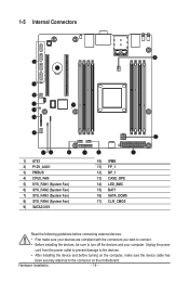
... connectors you wish to connect.
• Before installing the devices, be sure to turn off the devices and your computer. Unplug the power
cord from the power outlet to prevent damage to the devices.
• After installing the device and before turning on the computer, make sure the device cable has
been securely attached to the connector on the motherboard.
Hardware Installation
- 14 -
Manual - Page 15
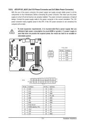
... on the motherboard. Before connecting the power connector, first make sure the power supply is turned off and all devices are properly installed. The power connector possesses a foolproof design. Connect the power supply cable to the power connector in the correct orientation. The 12V power connector mainly supplies power to the CPU. If the 12V power connector is not connected, the computer will...
Manual - Page 16
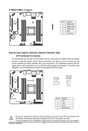
... design. When connecting a fan cable, be sure to connect it in the correct orientation (the black connector wire is the ground wire). The motherboard supports CPU fan speed control, which requires the use of a CPU fan with fan speed control design. For optimum heat dissipation, it is recommended that a system fan be installed inside the chassis.
SYS_FAN4
CPU0_FAN...
Manual - Page 17
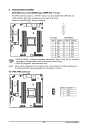
... SATA 3Gb/s and 1.5Gb/s standard. Each SATA connector supports a single SATA device. Please see page 22 for SATA DOM jumper setting.
7
SATA2 SATA3
SATA0 SATA1
Normal Mode:
1 SATA DOM Mode:
Pin No. 1 2 3 4 5 6 7
Definition GND TXP TXN GND RXN RXP GND
Pin No. 1 2 3 4 5 6 7
Definition GND TXP TXN GND RXN RXP P5V
• A RAID 0 or RAID 1 configuration requires at least two hard drives...
Manual - Page 18
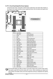
... power switch, reset switch, chassis intrusion switch/sensor and system status indicator on the chassis to this header according to the pin assignments below. Note the positive and negative pins before connecting the cables....CPU Switch NIC#2 Activity LED Cathode
The front panel design may differ by chassis. A front panel module mainly consists of power switch,
reset switch, power LED, hard drive...
Manual - Page 19
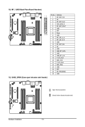
12) BP_1 (HDD Back Plane Board Hearders)
12 25 26
13) CASE_OPEN (Case open intrusion alert header)
Pin No. 1 2 3 4 5 6 7 8 9 10 11 12 13 14 15 16 17 18 19 20 21 ... BP_LED_G_N GND BP_SGP_DIN NC GND SMB_BP_DATA GND SMB_BP_CLK P_3V3_AUX BMC_ACK P_3V3_AUX BMC_REQ GND KEY BP_PRESENSE GND
Open: Normal operation. Closed: Active chassis intrustion alert.
Hardware Installation
- 19 -
Manual - Page 20
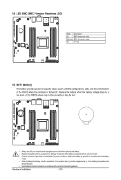
...firmware is initial
Blinking BMC firmware is ready
Off
AC loss
15) BAT1 (Battery)
The battery provides power to keep the values (such as BIOS configurations, date, and time information) in the CMOS when the computer...to replace the battery by yourself or uncertain about the battery
model. • When installing the battery, note the orientation of the positive side (+) and the negative side ...
Manual - Page 21
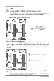
16) SATA_DOM0 (SATA port 3 Jumper)
CAUTION! • If the SATA DOM power is supplied by the motherboard, set the jumper to pin 1-2. • If the SATA DOM power is supplied by external power, set the jumper to pin 2-3. • If a SATA type hard drive is connected to the motherboard, please ensure the jumper is closed
and set to 2-3 pins (Default setting), in order to reduce any...