Gigabyte MW50-SV0 driver and firmware
Related Gigabyte MW50-SV0 Manual Pages
Download the free PDF manual for Gigabyte MW50-SV0 and other Gigabyte manuals at ManualOwl.com
Manual - Page 3
... Installing the CPU...14 1-3-2 Installing the CPU Cooler 17 1-4 Installing the Memory 18 1-4-1 Four Channel Memory Configuration 18 1-4-2 Installing a Memory 19 1-4-3 DIMM Population Table 19 1-5 Back Panel Connectors 20 1-6 Internal Connectors 21 1-7 Jumper Settings 32
Chapter 2 BIOS Setup 37 2-1 The Main Menu 39 2-2 Advanced Menu 41
2-2-1 Serial Port Console Redirection 42 2-2-2 PCI...
Manual - Page 6
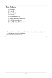
Box Contents
Motherboard Driver CD Two SATA cables I/O Shield Bracket mini PCI-e Card 2-way PCI-e bridge Crossfire cable 2-way PCI-e bridge SLI cable 3-way PCI-e bridge SLI small card
• The box contents above are for reference only and the actual items shall depend on the product package you obtain. The box contents are subject to change without notice.
• The motherboard image is for ...
Manual - Page 8
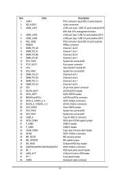
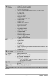
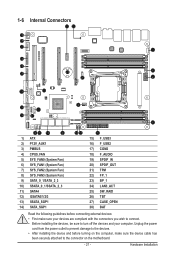
...Clear CMOS jumper System fan connector#2 System fan connector#1 Type A USB 3.0 connector SATA port 4 DOM support jumper USB3.0 header USB2.0 header Case open intrusion alert header SATA 3 6Gb/s connectors ME recovery jumper ME update jumper Software RAID Key header SATA 3 6Gb/s connectors HDD back plane board header LAN port 3 active LED header Front panel header Serial port cable connector
- 8 -
Manual - Page 11
... a motherboard, CPU or memory. If you do not have an ESD wrist strap, keep your hands dry and first touch a metal object to eliminate static electricity. • Prior to installing the motherboard, please have it on top of an antistatic pad or within an electrostatic shielding container. • Before unplugging the power supply cable from the motherboard, make...
Manual - Page 12
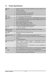
...® 88SE9230 controller 4 x SATA3 6Gb/s connectors (GSATA0/1/2/3) support for SATA RAID 0/1/10 Up to 7 USB 3.0 ports (1 Type A connector, 4 on the back panel, 2 additional ports via the USB brackets connected to the internal USB headers) Up to 6 USB 2.0 ports (4 on the back panel, 2 additional ports via the USB brackets connected to the internal USB headers)
Hardware Installation
- 12 -
Manual - Page 13
... Serial port connector ŠŠ 1 x Front audio connector ŠŠ 1 x Thunderbolt connector ŠŠ 2 x SATA SPGIO headers ŠŠ 1 x S/PDIF in header ŠŠ 1 x S/PDIF out header ŠŠ 1 x Software RAID key connector ŠŠ 1 x LAN3 Active LED header ŠŠ 1 x Chassis intrusion alert header ŠŠ 4 x USB 3.0 ports ŠŠ 4 x USB 2.0 ports...
Manual - Page 14
... not recommended
that the system bus frequency be set beyond hardware specifications since it does not meet the standard requirements for the peripherals. If you wish to set the frequency beyond the standard specifications, please do so according to your hardware specifications including the CPU, graphics card, memory, hard drive, etc.
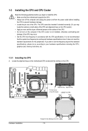
1-3-1 Installing the CPU
A. Locate the alignment keys on...
Manual - Page 15
... steps below to correctly install the CPU into the motherboard CPU socket. •• Before installing the CPU, make sure to turn off the computer and unplug the power cord from the power outlet to prevent damage to the CPU.
•• To protect the socket contacts, do not remove the protective plastic cover unless the CPU is inserted into the...
Manual - Page 16
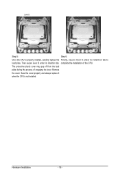
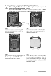
... properly inserted, carefully replace the Finally, secure lever A under its retention tab to
load plate. Then secure lever B under its retention tab. complete the installation of the CPU.
The protective plastic cover may pop off from the load
plate during the process of engaging the lever. Remove
the cover. Save the cover properly and...
Manual - Page 17
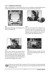
... below to correctly install the CPU cooler on the motherboard. (Actual installation process may differ depending the CPU cooler to be used. Refer to the user's manual for your CPU cooler.)
Step 1:
Step 2:
Apply an even and thin layer of thermal grease on the Place the cooler atop the CPU, aligning the four
surface of the installed CPU.
mounting screws...
Manual - Page 18
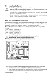
... you begin to install the memory: • Make sure that the motherboard supports the memory. It is recommended that memory of the
same capacity, brand, speed, and chips be used. • Always turn off the computer and unplug the power cord from the power outlet before installing
the memory to prevent hardware damage. • Memory modules have a foolproof design. A memory module can be...
Manual - Page 19
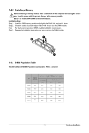
1-4-2 Installing a Memory
Before installing a memory module, make sure to turn off the computer and unplug the power cord from the power outlet to prevent damage to the memory module. Be sure to install DDR4 DIMMs on this motherboard. Installation Step: Step 1. Insert the DIMM memory module vertically into the DIMM slot, and push it down. Step 2. Close the plastic clip at both edges...
Manual - Page 20
...
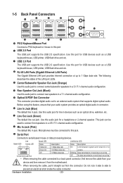
The USB port supports the USB 2.0 specification. Use this port for USB devices such as a USB
keyboard/mouse, USB printer, USB flash drive and etc.
RJ-45 LAN Ports (Gigabit Ethernet LAN Ports)
The Gigabit Ethernet LAN port provides Internet connection at up to 1 Gbps data rate. The following
describes the states of the LAN port LEDs.
Center/Subwoofer Speaker Out Jack (Orange)
Use this audio...
Manual - Page 21
... the connectors you wish to connect. • Before installing the devices, be sure to turn off the devices and your computer. Unplug the power
cord from the power outlet to prevent damage to the devices. • After installing the device and before turning on the computer, make sure the device cable has
been securely attached to the connector on the motherboard.
- 21 -
Hardware...
Manual - Page 34
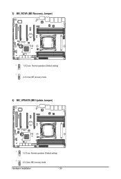
3) ME_RCVR (ME Recovery Jumper)
ME_RCVR
1
1-2 Close: Normal operation.(Default setting)
1 2-3 Close: ME recovery mode.
4) ME_UPDATE (ME Update Jumper)
ME_UPDATE
1 1-2 Close: Normal operation (Default setting)
1
2-3 Close: ME recovery mode.
Hardware Installation
- 34 -
Manual - Page 71
... 0/1Version
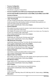
Displays the technical specifications for the installed processor. Hyper-Threading [All]
The Hyper Threading Technology allows a single processor to execute two or more separate threads concurrently. When hyper-threading is enabled, multi-threaded software applications can execute their threads, thereby improving performance. Options available: Enabled/Disabled. Default setting is...
Manual - Page 106
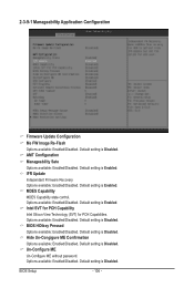
... Configuration
Firmware Update Configuration Me FW Image Re-Flash Options available: Enabled/Disabled. Default setting is Disabled. AMT Configuration Manageability Sate Options available: Enabled/Disabled. Default setting is Enabled. IFR Update Independant Firmware Recovery. Options available: Enabled/Disabled. Default setting is Enabled. MDES Capability MDES Capability state control. Options...
Manual - Page 114

... the
range 1 to 33. Press / keys to increase or decrease the desired values. METW
Multiple Event Time Window: The number of minutes which must pass between duplicate log entries
which utilize a multiple-event counter. The value ranges from 0 to 99 minutes. Press / keys to
increase or decrease the desired values.
BIOS Setup
- 114 -
Manual - Page 117
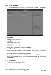
...-signed with valid digital certificates. This way, the system knows all the files being loaded before Windows 8 loads and gets to the login screen have not been tampered with. When set to Standard, it will automatically load the Secure Boot keys form the BIOS databases. When set to Custom, you can customize the Secure Boot settings and manually load its keys...
Manual - Page 128
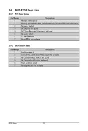
... not found DXE Core Firmware Volume was not found Recovery failed S3 Resume failed Reset PPI is not available
2-9-2 DEX Beep Codes
# of Beeps 1 4 5 5 6 7
Description Invalid password Some of the Architectural Protocols are not available No Console Output Devices are found No Console Input Devices are found Flash update is failed Reset protocol is not available
BIOS Setup
- 128 -