Sony HCD-HPX7 driver and firmware

Related Sony HCD-HPX7 Manual Pages
Download the free PDF manual for Sony HCD-HPX7 and other Sony manuals at ManualOwl.com
Service Manual - Page 2
HCD-HPX7
TABLE OF CONTENTS
1. SERVICING NOTES 4
2. GENERAL 5
3. DISASSEMBLY 3-1. Disassembly Flow-1 7 3-2. Disassembly Flow-2 8 3-3. Optical Pick-Up Block 9 3-4. Side Plate (L) (R), Top Panel Section 10 3-5. Mechanical Deck 11 3-6. Front Panel Section 12 3-7. PANEL (1), (2) Board, HEADPHONE Board 12 3-8. Tuner (FM/AM), DC Fan 13 3-9. MAIN Board 14 3-10. Rear Panel Section 14 3-11. ...
Service Manual - Page 5
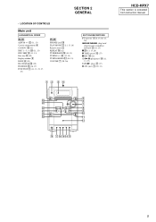
... DESCRIPTIONS
?/1 (power) 1 (8, 15, 20, 21, 28)
.m/M> (skip back/ skip forward, rewind/fast forward) 8 (11, 13)
x wd (11, 15, 28) X TAPE (pause) qd (17) z REC qf (18) CD/NX (play/pause) ql (11,
13, 27) TAPE/N (play) wa (17) Z (CD eject) qa (10, 11)
12 34
HCD-HPX7
This section is extracted from instruction manual.
+/1
wf...
Service Manual - Page 8
HCD-HPX7
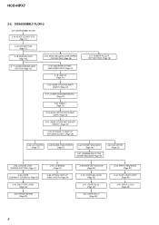
3-2. DISASSEMBLY FLOW-2
from DISASSEMBLY FLOW-1
3-14. PLATE (COVER TOP) (Page 17)
3-15. TOP SECTION (Page 17)... (Page 30)
3-33. CHASSIS (TOP), CHASSIS (BOTTOM) (Page 31)
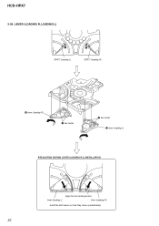
3-34. LEVER (LOADING R, LOADING L) (Page 32)
3-35. DISC STOP LEVER (Page 33)
3-36. DRIVER BOARD (Page 33)
3-37. CD BOARD (Page 34)
3-38. OPTICAL PICK-UP (KSM-215DCP) (Page 34)
3-39. BASE UNIT SECTION (Page 35)
3-40....
Service Manual - Page 18
HCD-HPX7
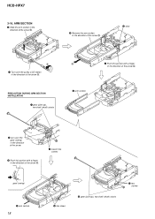
3-16. ARM SECTION
2 Slide the arm section in the direction of the arrow B.
B
A 1 Turn over the pulley (LOD ...the direction of the arrow D.
3 claw C
D
4 Push this portion with a finger
in the direction of the arrow C.
PRECAUTION DURING ARM SECTION INSTALLATION
1 gear (joint op), two shaft (shaft) stocks
6 arm section
3 turn over the gear (swing) in the direction of the arrow.
6 Push...
Service Manual - Page 32
HCD-HPX7
3-34. LEVER (LOADING R, LOADING L)
2 SPR-T (loading L)
1 SPR-T (loading R)
6 lever (loading R)
5 two hooks
3 two hooks 4 lever (loading L)
PRECAUTION DURING LEVER (LOADING R/L) INSTALLATION
Align the horizontal position.
lever (loading L)
lever (loading R)
Install the both levers so that they move symmetrically.
32
Service Manual - Page 33
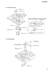
3-35. DISC STOP LEVER
1 gear (cap) 2 gear (IDL L)
HCD-HPX7
5 two hooks 6 disc stop lever
PRECAUTION DURING DISC STOP LEVER INSTALLATION chassis (top)
hole
3 two claws 4 disc sensor lever
disc stop lever hole
Install the disc stop lever so that the both holes are aligned.
3-36. DRIVER BOARD
3 Remove soldering from the two points.
4 motor (pulley) assy...
Service Manual - Page 38
HCD-HPX7
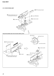
3-44. PLATE (PUSH) ASSY
5 Remove the plate (push) assy in the direction of the arrow. 4 four claws
1 SPR-E (plate-push-back)
2 screw (PTPWH M2) 3 gear (tako second)
PRECAUTION DURING GEAR (TAKO SECOND) INSTALLATION
Adjust phases.
plate (push) assy
3 SPR-E (plate-push-back)
gear (tako second) 4 gear (tako second)
1 Remove the plate (push...
Service Manual - Page 39
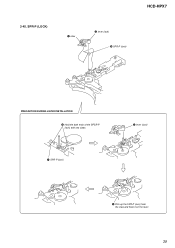
3-45. SPR-P (LOCK)
1 claw
2 lever (lock) 3 SPR-P (lock)
HCD-HPX7
PRECAUTION DURING LEVER INSTALLATION 2 Hold the both ends of the SPSR-P (lock) with two claws.
1 SPR-P (lock)
3 lever (lock)
4 Pick up the SPR-P (lock) from the claw and hook it on the lever.
39
Service Manual - Page 41
HCD-HPX7
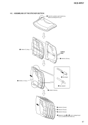
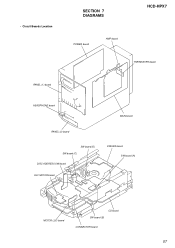
4-2. ASSEMBLING OF THE STOCKER SECTION
1 Check the number on each stocker assy, before assembling all the assys.
2 stocker (1) assy 6 stocker (1) assy
UPPER SIDE 3 stocker (2) assy
5 tow claws
4 tow dowels 7 stocker (2) assy
8 stocker (3) assy 9 stocker (4) assy 0 stocker (5) assy 1 Repeat the steps 4 to 6, when installing the part
(2), (3), (4) and (5) of the stocker assy.
41
Service Manual - Page 42
HCD-HPX7
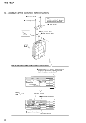
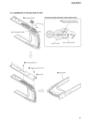
4-3. ASSEMBLING OF THE GEAR (STOCK ROT SHORT) (RIGHT)
7 two screws (2 × 6) 8 screw (1.7)
Note: Install the stock box (R) right after finishing the phase adjustment.
6 stock box (R)
short
4 gear (stock rot short) 2 gear (stock rot short)
UPPER SIDE
PRECAUTION DURING GEAR (STOCK ROT SHORT) INSTALLATION
1 Align the edges of the stockers. Keep the position of...
Service Manual - Page 43
HCD-HPX7
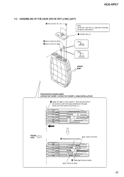
4-4. ASSEMBLING OF THE GEAR (STOCK ROT LONG) (LEFT)
6 two screws (2 × 6)
Note. Install the stock box (L) right after finishing the phase adjustment.
7 stocker box (L)
2 gear (stock rot short) 4 gear (stock rot long)
short
long
UPPER SIDE
PRECAUTION DURING GEAR (STOCK ROT SHORT, STOCK ROT SHORT LONG) INSTALLATION
1 Align the edges of the stockers...
Service Manual - Page 45
HCD-HPX7
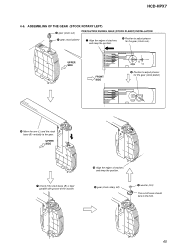
4-6. ASSEMBLING OF THE GEAR (STOCK ROTARY LEFT)
2 gear (stock sun)
PRECAUTION DURING GEAR (STOCK PLANET) INSTALLATION
4 gear (stock planet)
1 Align the edges of stockers, and keep the position.
3 Position to adjust phases for the gear (stock sun).
UPPER SIDE
FRONT SIDE
5 ...
Service Manual - Page 46
HCD-HPX7
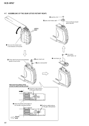
4-7. ASSEMBLING OF THE GEAR (STOCK ROTARY RIGHT)
qa washers (5.5) 0 gear (stock rotary right)
UPPER SIDE
The...gear (stock sun) 6 gear (stock planet)
8 stock base (A)
9 two screws (BTTP M2.6 × 6)
PRECAUTION DURING GEAR (STOCK PLANET) INSTALLATION
5 Position to adjust phases for the gear (stock sun).
2 Keep the position of the edges of the stockers and adjust phases.
7 Position to...
Service Manual - Page 47
HCD-HPX7
4-8. ASSEMBLING OF THE LEVER (SUB GEAR BACK L)
PRECAUTION DURING SPR-T (SUB GEAR BACK L) INSTALLATION
1 Turn over the stocker assy in the direction of the arrow.
lever (sub gear back L) gear (sub gear pin left)
gear (stock rotary left)
PRECAUTION DURING GEAR (SUB GEAR PIN LEFT) INSTALLATION
gear (sub gear pin left) 2 Adjust phases...
Service Manual - Page 48
HCD-HPX7
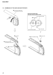
4-9. ASSEMBLING OF THE GEAR (SUB GEAR PIN RIGHT)
1 Turn over the stocker assy in the direction of the arrow.
UPPER SIDE
PRECAUTION DURING GEAR (SUB GEAR PIN RIGHT) INSTALLATION
gear (sub gear pin right) 6 Adjust phases.
4 two screws (2 × 5)
2 Remove the arm (R) in the direction of the arrow.
3 two dowels
gear (stock...
Service Manual - Page 49
HCD-HPX7
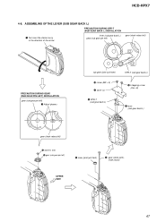
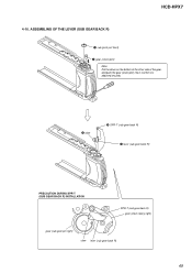
4-10. ASSEMBLING OF THE LEVER (SUB GEAR BACK R)
1 sub (joint just front)
2 gear (stock joint) Note: Put the driver on the bottom of the other side of... the gear, and push the gear (stock joint) into it. Confirm it is attached securely.
3 claw
5 SPR-T (sub gear back R) 4 lever (sub gear back R)
PRECAUTION DURING SPR-T (SUB GEAR BACK R) INSTALLATION...
Service Manual - Page 51
HCD-HPX7
4-12. ASSEMBLING OF THE SUB GEAR (2 STEP)
1 sub gear (2 step)
hole hole
PRECAUTION DURING SUB GEAR (2 STEP) INSTALLATION
2 Align the sub gear (2 step) and the gear (sub gear pin right) hole.
gear (sub gear pin right)
hole
sub gear (2 step)
gear (sub gear pin right)
5 two screws (M2 × 5) 4 k tapping screw (2.6 × 8) 3 cover (R)
6 arm section
51
Service Manual - Page 57
• Circuit Boards Location
SECTION 7 DIAGRAMS
HCD-HPX7
POWER board
AMP board THERMISTER board
PANEL (1) board
HEADPHONE board
MAIN board
PANEL (2) board
SW board (D) SW board (C) DISC ADDRESS SW board
ELV MOTOR board
DRIVER board SW board (A)
MOTOR LOD board
CD board SW board (B) CONNECTOR board
57
Service Manual - Page 61
...
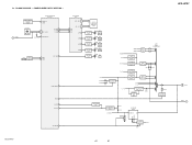
RECT D906 - 909
FL AC FL AC
-30V REGULATOR Q805 - 807
CURRENT LIMIT Q808
RECT D910
D912
RY901
RELAY DRIVE Q319, 320
RESET SWITCH Q316
VOLTAGE DETECT IC305
U-COM B+
D306 D308
SWITCH Q321
SUB POWER BLOCK
U COM +B AC
SW SW 9V
B+ SWITCH Q322, 323
D327
A+9V
HCD-HPX7
61
61
HCD-HPX7
(AC IN)
AC DET C
Service Manual - Page 64
...
1
2
3
4
5
6
7
A
(LOD POSITION/CLOSE)
B
C
(8cm)
D
(12cm)
E
(OPEN) (PUSH-CLOSE)
F
G H
HCD-HPX7
M
(LOADING)
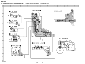
IC811
MAIN BOARD CN315 (Page 66)
(DISC 5) (DISC 3) (DISC 1)
(DISC (+1)) (DISC 4) (DISC 2)
64
64
IC801 R701 1-688-337-
8
9
10
11
DRIVER BOARD
S702 (CHUCK)
9
IC701
S701 (OUT)
R702
1 D701
C705 C711
M
M701
(LOADING)
CN701
B MAIN BOARD
CN303 (Page 66)
M (ELV) ELV