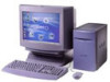
Sony PCV-E204 - Vaio Desktop Computer driver and firmware
Related Sony PCV-E204 Manual Pages
Download the free PDF manual for Sony PCV-E204 and other Sony manuals at ManualOwl.com
Reference Manual - Page 2
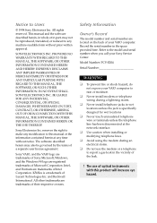
... are located on the back of your VAIO computer. Record the serial number in the space provided here. Refer to the model and serial number when you call your Sony Service Center.
Model Number: PCV-E204
Serial Number
WARNING
u To prevent fire or shock hazard, do
not expose your VAIO computer to rain or moisture.
u Never install modem or telephone
wiring during a lightning storm...
Reference Manual - Page 3
...
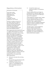
Declaration of Conformity
Trade Name: SONY Model No.: PCV-E204 Responsible Party: Sony Electronics Inc. Address: 1 Sony Drive Park Ridge, NJ 07656 Telephone No: 201-930-6970
This device complies with Part 15 of FCC Rules. Operation is subject to the two following conditions: (1) This device may not cause harmful interference, and (2) this device must accept any interference received, including...
Reference Manual - Page 4
....
Repair of the modem should be made only by a Sony Service Center or Sony authorized agent. For the Sony Service Center nearest you, call 1-800-222-SONY (1-800-222-7669).
Telephone Consumer Protection Act of 1991
The Telephone Consumer Protection Act of 1991 makes it unlawful for any person to use a computer or other electronic device to send any...
Reference Manual - Page 5
... iv
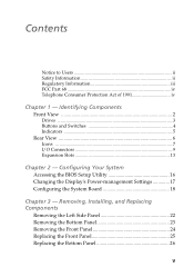
Chapter 1 - Identifying Components
Front View 2 Drives 3 Buttons and Switches 4 Indicators 5
Rear View 6 Icons ...7 I/O Connectors 9 Expansion Slots 13
Chapter 2 - Configuring Your System
Accessing the BIOS Setup Utility 16 Changing the Display's Power-management Settings 17 Configuring the System Board 18
Chapter 3 - Removing, Installing, and Replacing Components
Removing the Left...
Reference Manual - Page 6
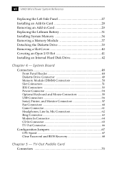
... Power Connector 54 Optional Keyboard and Mouse Connectors 55 USB Connectors 56 Serial, Printer, and Monitor Connectors 57 Fan Connectors 60 Game Connector 61 Headphones, Line In, Mic Connectors 62 Ring Connector 63 Modem In Connector 64 CD In Connector 65 TV Out Connector 66
Configuration Jumpers 67 CPU Speed 67 Clear Password and BIOS Recovery 68
Chapter 5 - TV-Out Paddle Card...
Reference Manual - Page 24
16 VAIO MicroTower System Reference
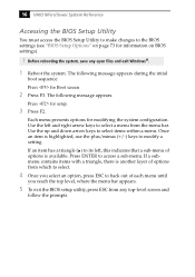
Accessing the BIOS Setup Utility
You must access the BIOS Setup Utility to make changes to the BIOS settings (see "BIOS Setup Options" on page 73 for information on BIOS settings).
! Before rebooting the system, save any open files and exit Windows®.
1 Reboot the system. The following message appears during the inital
boot sequence:
Press for Boot...
Reference Manual - Page 26
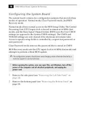
... Password mode removes the password that is stored in CMOS.
BIOS Recovery mode sets the CPU input clock to 66 MHz (fast mode) and attempts to perform a blind BIOS update.
The configuration jumpers should never need changing unless otherwise directed by a
technical support or service technician.
! Before opening the system, save any open files, exit Windows, turn off the
power of the computer...
Reference Manual - Page 29
Chapter 3 Removing, Installing, and Replacing Components
This chapter describes removing, installing, and replacing major components for upgrading, reconfiguring, replacing, or troubleshooting the components.
! Before opening the system unit, save any open files, exit Windows, turn off
the power of the computer and all attached peripherals, and then unplug the power cord.
21
Reference Manual - Page 31
Removing, Installing, and Replacing Components 23
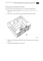
Removing the Bottom Panel
You must remove the bottom panel to access internal components.
1 Remove the left side panel (see "Removing ...
Reference Manual - Page 32
24 VAIO MicroTower System Reference
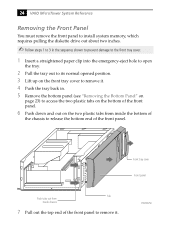
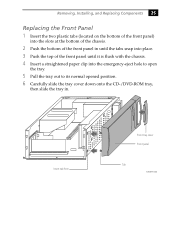
Removing the Front Panel
You must remove the front panel to install system memory, which requires pulling the diskette drive out about two inches.
Follow steps 1 to 3 in the sequence shown to prevent damage to the front tray cover.
1 Insert a straightened paper clip into the ...
Reference Manual - Page 33
Removing, Installing, and Replacing Components 25
Replacing the Front Panel 1 Insert the two plastic tabs (located on the bottom of the front panel)
into the slots at ...-eject hole to open
the tray.
5 Pull the tray out to its normal opened position. 6 Carefully slide the tray cover down onto the CD-/DVD-ROM tray,
then slide the tray in.
Insert tab here
Front tray cover Front panel
Tab
KY0077.VSD
Reference Manual - Page 35
Removing, Installing, and Replacing Components 27
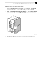
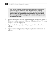
Replacing the Left Side Panel 1 Position the left side panel against the side of the unit, with the left
side panel ...
Reference Manual - Page 36
28 VAIO MicroTower System Reference
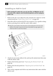
Installing an Add-In Card ! Before opening the system unit, save any open files, exit Windows, turn off
the power of the computer and all attached peripherals, and then unplug the power cord.
1 Remove the slot cover adjacent to the selected slot connector on the
system board (see "Removing a Slot Cover" on page 40...
Reference Manual - Page 37
...Installing, and Replacing Components 29
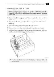
Removing an Add-in Card ! Before opening the system unit, save any open files, exit Windows, turn off
the power of the computer and all attached peripherals, and then unplug the power... cables attached to the add-in card. 4 Remove the screw that secures the add-in card to the chassis. 5 Remove the add-in card from the PCI slot connector and store the
card in...
Reference Manual - Page 38
... exposed metal part on the metal chassis (preferably the metal part on the power supply) before handling an add-in card to discharge any static electricity in your body.
6 If you do not replace the card or install another add-in card, install a
slot cover over the vacant slot at the rear of the chassis (see...
Reference Manual - Page 39
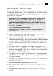
... lithium battery if your computer consistently loses the date or time settings after turning it off. The lithium battery has a typical life of three years, after which the battery may be too weak to power the CMOS memory.
! When you remove the lithium battery, all values stored in the CMOS memory
(BIOS setup values and Plug and...
Reference Manual - Page 42
34 VAIO MicroTower System Reference
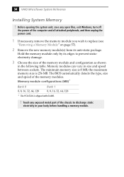
Installing System Memory
! Before opening the system unit, save any open files, exit Windows, turn off
the power of the computer and all attached peripherals, and then unplug the power cord.
1 If necessary, remove the memory module you wish to replace (see
"Removing a Memory Module" on page 37).
2 Remove the new memory module(s) from its anti...
Reference Manual - Page 45
Removing, Installing, and Replacing Components 37
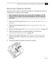
Removing a Memory Module
You may need to remove a memory module if you change the memory configuration or replace a bad module.
! Before opening the system unit, save any open files, exit Windows, turn off
the power of the computer and all attached peripherals, and then unplug the power cord.
1 Remove the left side panel...
Reference Manual - Page 50
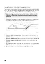
... with an available bay to hold an additional hard disk drive. The drive you install must not require front panel access. The hard disk drive access light blinks when either internal drive is active.
! Before opening the system unit, save any open files, exit Windows, turn off
the power of the computer and all attached peripherals, and then unplug the...
Reference Manual - Page 109
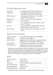
...- adapter cable not supplied)
Two RJ-11 connectors (for line and phone)
USB 1 and USB 2
Two available slots. Maximum length for add-in cards is 7.75 inches
One (occupied by fax/modem card). Maximum length for add-in card is 10.5 inches.
Primary and Secondary (each supports two IDE drives)
Drives and Controllers
Diskette controller Diskette drive EIDE controller
IDE hard drive DVD-ROM drive
765A...