ASRock K8Upgrade-PCIE driver and firmware
Drivers and firmware downloads for this ASRock item
Related ASRock K8Upgrade-PCIE Manual Pages
Download the free PDF manual for ASRock K8Upgrade-PCIE and other ASRock manuals at ManualOwl.com
User Manual - Page 3
... CPU Installation 11 2.2 Installation of CPU Fan and Heatsink 11 2.3 Installation of Memory Modules (DIMM 12 2.4 Expansion Slots (Future CPU Port, PCI and PCI Express Slots) ..... 13 2.5 Jumpers Setup 15 2.6 Onboard Headers and Connectors 16 2.7 Serial ATA (SATA) Hard Disks Installation 19 2.8 Making a SATA Driver Diskette For SATA Operation in "RAID"
Mode 20 2.9 SATA Operating in "non-RAID...
User Manual - Page 5
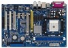
... Package Contents
1 x ASRock K8Upgrade-PCIE Motherboard (ATX Form Factor: 12.0-in x 8.0-in, 30.5 cm x 20.3 cm)
1 x ASRock K8Upgrade-PCIE Quick Installation Guide 1 x ASRock K8Upgrade-PCIE Support CD 1 x Ultra ATA 66/100/133 IDE Ribbon Cable (80-conductor) 1 x 3.5-in Floppy Drive Ribbon Cable 1 x Serial ATA (SATA) Data Cable (Optional) 1 x Serial ATA (SATA) HDD Power Cable (Optional) 1 x ASRock 8CH...
User Manual - Page 6
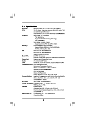
... up to 4 IDE Devices
Serial ATA:
2 x SATA Connectors
Supports up to 2 SATA Devices at 1.5Gb/s Data Transfer Rate
Floppy Port:
Supports up to 2 Floppy Disk Drives
Audio:
7.1 channels AC'97 Audio
LAN:
Speed: 802.3u (10/100 Ethernet), Supports Wake-On-LAN
Hardware Monitor: CPU Temperature Sensing
Motherboard Temperature Sensing
CPU Overheat Shutdown to Protect CPU Life
(ASRock U-COP)(see...
User Manual - Page 7
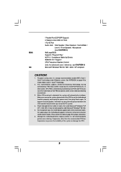
... grease between the CPU and the heatsink when you install the PC system.
4. Power Management for USB 2.0 works fine under Microsoft® Windows® XP SP1 / 2000 SP4. It may not work properly under Microsoft® Windows® 98/ ME.
5. For microphone input, this motherboard supports both stereo and mono modes. For audio output, this motherboard supports 2-channel, 4-channel, 6-channel...
User Manual - Page 10
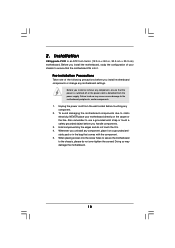
2. Installation
K8Upgrade-PCIE is an ATX form factor (12.0-in x 8.0-in, 30.5 cm x 20.3 cm) motherboard. Before you install the motherboard, study the configuration of your chassis to ensure that the motherboard fits into it.
Pre-installation Precautions
Take note of the following precautions before you install motherboard components or change any motherboard settings.
Before you install or remove ...
User Manual - Page 11
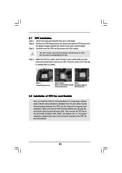
... grease between the CPU and the heatsink to improve heat dissipation. Make sure that the CPU and the heatsink are securely fastened and in good contact with each other. Then connect the CPU fan to the CPU FAN connector (CPU_FAN1, see Page 8, No. 3). For proper installation, please kindly refer to the instruction manuals of the CPU fan and...
User Manual - Page 12
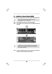
2.3 Installation of Memory Modules (DIMM)
This motherboard is equipped with two 184-pin DDR (Double Data Rate) DIMM slots. Please make sure to disconnect power supply before adding or removing DIMMs or the system ...
The DIMM only fits in one correct orientation. It will cause permanent damage to the motherboard and the DIMM if you force the DIMM into the slot at incorrect orientation. Step ...
User Manual - Page 13
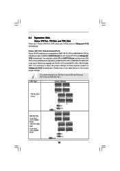
... 1 Future CPU Port, 3 PCI slots and 3 PCIE slots on K8Upgrade-PCIE motherboard.
Future CPU Port (Yellow-Colored Port): Future CPU Port allows you to upgrade your AMD 754-Pin CPU to AMD 939-Pin CPU by installing an add-on ASRock 939CPU Board into this future CPU Port on K8UpgradePCIE motherboard. You may also install ASRock M2CPU Board into this future CPU Port on this motherboard to upgrade your...
User Manual - Page 14
... your motherboard package, and please follow the "Jumper Cap Remover Instruction" to use it properly. PCI Slots: PCI slots are used to install expansion cards that have the 32-bit PCI
interface. PCIE Slots: PCIE1 (PCIE x16 slot) is used for PCI Express cards with x16 lane
width graphics cards. PCIE2 / PCIE3 (PCIE x1 slot) is used for PCI Express cards, such as Gigabit LAN card, SATA II card...
User Manual - Page 15
... 2 pins.
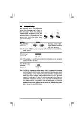
Jumper
Setting
PS2_USB_PW1
1_2
2_3
Short pin2, pin3 to enable
(see p.8, No. 1)
+5V
+5VSB
+5VSB (standby) for PS/2 or USB wake up events....setup, please turn off the computer and unplug the power cord from the power supply. After waiting for 15 seconds, use a jumper cap to short 2 pins on CLRCMOS2 for 5 seconds. However, please do not clear the CMOS right after you update the BIOS...
User Manual - Page 18
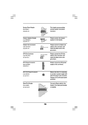
...(see p.8 No. 19)
CPU Fan Connector
(3-pin CPU_FAN1) (see p.8 No. 3)
ATX Power Connector
(20-pin ATXPWR1)...power supply with ATX 12V plug to this connector. Failing to do so will cause power up failure.
Game Port Header
(15-pin GAME1) (see p.8 No. 24)
+5V JBB1 JBX MIDI_OUT JBY JBB2 MIDI_IN
1
+5V JAB2 JAY GND GND JAX JAB1 +5V
Connect a Game cable to this header if the Game port bracket is installed...
User Manual - Page 19
2.7 Serial ATA (SATA) Hard Disks Installation
This motherboard supports Serial ATA (SATA) hard disks and RAID functions. This section will guide you to install the SATA hard disks. STEP 1: Install the SATA hard disks into the drive bays of your chassis. STEP 2: Connect the SATA power cable to the SATA hard disk. STEP 3: Connect one end of the SATA data cable to the motherboard's SATA
connector. ...
User Manual - Page 20
... with RAID functions, you will need to make a SATA driver before you start the OS installation. STEP 1: Insert the ASRock Support CD into your optical drive to boot your system.
(Do NOT insert any floppy diskette into the floppy drive at this moment!) STEP 2: During POST at the beginning of system boot-up, press key, and
then a window for boot devices...
User Manual - Page 21
...
This section explains how to use the BIOS SETUP UTILITY to configure your system. The Flash Memory on the motherboard stores the BIOS SETUP UTILITY. You may run the BIOS SETUP UTILITY when you start up the computer. Please press during the Power-On-Self-Test (POST) to enter the BIOS SETUP UTILITY, otherwise, POST will continue with its test routines. If you...
User Manual - Page 22
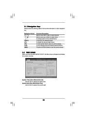
... will appear and display the system overview.
BIOS SETUP UTILITY Main Advanced H/W Monitor Boot Security Exit
System Overview
System Time System Date
[17:00:09] [Tue 05/31/2005]
BIOS Version : K8Upgrade-PCIE BIOS P1.0 Processor Type : AMD Athlon(tm) 64 Processor 3400+ Processor Speed : 2200 MHz Microcode Update : F7A/3A L1 Cache Size : 128KB L2 Cache Size : 1024KB
Total Memory DDR 1 DDR...
User Manual - Page 23
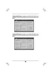
...ASRock 939CPU Board is installed into the FUTURE_CPU_PORT on this motherboard, you will see the below Main screen when entering the BIOS SETUP UTILITY.
BIOS SETUP UTILITY Main Advanced H/W Monitor Boot Security Exit
System Overview
System Time System Date
[17:00:09] [Tue 05/31/2005]
BIOS Version Processor Type Processor Speed Microcode Update L1 Cache Size L2 Cache Size
: K8Upgrade-PCIE BIOS...
User Manual - Page 30
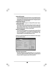
...if you plug PCIE-SATA2 card to this motherboard, the IDE Configuration screen will be as below.
Advanced
BIOS SETUP UTILITY
IDE Configuration
OnBoard IDE Controller OnBoard SATA Controller
SATA Operation Mode PCIE-SATA2 Operation Mode
Primary IDE Master Primary IDE Slave Secondary IDE Master Secondary IDE Slave SATA1 SATA2 PCIE-SATA2 Card
[Both] [Enabled] [RAID] [IDE]
[Hard Disk] [Not Detected...
User Manual - Page 31
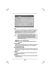
... item to configure the type of the IDE device that you specify. Configuration options: [Not Installed], [Auto], [CD/DVD], and [ARMD]. [Not Installed]: Select [Not Installed] to disable the use of IDE device. [Auto]: Select [Auto] to automatically detect the hard disk drive.
After selecting the hard disk information into BIOS, use a disk utility, such as FDISK, to partition and...
User Manual - Page 39
... BIN folder in the Support CD to display the menus.
4.2.2 Drivers Menu
The Drivers Menu shows the available devices drivers including ASRock Express GbL PCI Express LAN card driver if the system detects the installed devices. Please install the necessary drivers to activate the devices.
4.2.3 Utilities Menu
The Utilities Menu shows the applications software that the motherboard supports. Click on...
User Manual - Page 40
... feature, please make sure to install "AMD Processor Driver" from the "Support CD" first.
If you are using Windows 2000/XP operating system, please follow the instruction below to enable AMD's Cool 'n' QuietTM technology:
1. From the Windows 2000/XP operating system, click the Start button. Select Settings, then Control Panel.
2. Switch to Classic View. (for Windows XP only) 3. Double-click...