Asus V4-P5G45 driver and firmware

Related Asus V4-P5G45 Manual Pages
Download the free PDF manual for Asus V4-P5G45 and other Asus manuals at ManualOwl.com
Installation Manual - Page 1
English
V4-Series
ASUS PC (Desktop Barebone)
Installation manual
Installation Manual - Page 2
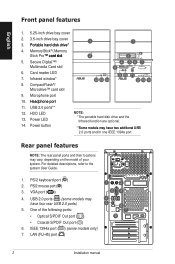
... Card slot 6. Card reader LED 7. Infrared window* 8. CompactFlash®/
Microdrive™ card slot 9. Microphone port 10. He��a�d�p�h�o�n�e��p�o�r�t 11. USB 2.0 ports** 12. HDD LED 13. Power LED 14. Power button
1
1
2
3
4 56 7 8
12 13 14
9 10 11 12 13 14
NOTE: * The portable hard disk drive...
Installation Manual - Page 3
...• E-SATA port (
)
• Serial (COM1) port ( )
• DVI port (
)
• HDMI port ( )
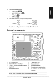
9. One of the following audio ports configurations:
• 6-channel
• 8-channel
Refer to the configuration table in the User Guide for details.
Internal components
5
6 7
8
2
1
3 4
9
1. Front panel cover 2. 5.25-inch optical drive bays 3. 2.5-inch portable hard disk drive bay...
Installation Manual - Page 4
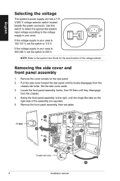
...your area is 100‑127 V, set the switch to 115 V.
If the voltage supply in your area is 200‑240 V, set the switch to 230 V.
NOTE: Refer to the system User Guide for the exact location of the ... side of the assembly are exposed. 5. Remove the front panel assembly, then set aside.
Air �d�u�c�t
1
3
4
2
1 2
Chassis tab holes
4 3
4 3
4
Installation manual
Installation Manual - Page 5
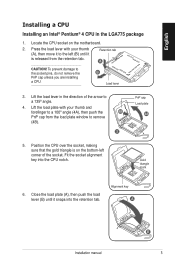
...CPU socket on the motherboard.
2. Press the load lever with your thumb (A), then move it to the left (B) until it is released from the retention tab.
Retention tab A
CAUTION! To prevent damage to the socket pins, do not remove the PnP cap unless you are installing a CPU.
B Load lever
3. Lift the load... the load plate window to remove
(4B).
3
PnP cap Load plate
4A
5. Position the CPU over ...
Installation Manual - Page 6
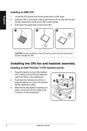
... on top of the installed CPU, making sure that the four fasteners match the holes on the motherboard.
2. Push down two fasteners at a time in a diagonal sequence to secure the heatsink and fan assembly in place.
3. When the fan and heatsink assembly is in place, connect the CPU fan cable to the connector on the motherboard.
A B
B A
1 1
Installation manual
Installation Manual - Page 7
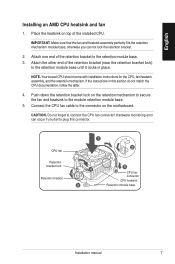
... the fan and heatsink to the module retention module base.
5. Connect the CPU fan cable to the connector on the motherboard.
CAUTION. Do not forget to connect the CPU fan connector! Hardware monitoring error can occur if you fail to plug this connector.
CPU fan
Retention bracket lock
Retention bracket
1 2
4 3
5
CPU fan connector CPU heatsink Retention module base
Installation manual
Installation Manual - Page 8
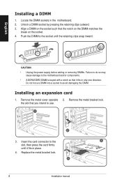
...clips snap inward.
CAUTION: • Unplug the power supply before adding or removing DIMMs. Failure to do so may cause damage to the motherboard and/or components. • A DDR2/DDR3 ...DIMM is keyed with a notch so that it fits in only one direction. Do not force a DIMM into a socket to avoid damaging the DIMM.
Installing an expansion card...
Installation Manual - Page 9
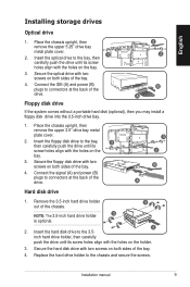
... the holes on the bay.
3. Secure the optical drive with two screws on both sides of the bay.
4. Connect the IDE (A) and power (B) plugs to connectors at the back of the drive.
Floppy disk drive
2 3
B A
If the system comes without a portable hard disk (optional), then you may install a floppy disk drive into the 3.5-inch drive bay.
1. Place the chassis upright, then...
Installation Manual - Page 10
English
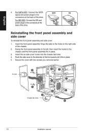
4. For SATA HDD: Connect the SATA
SATA
IDE
signal and power plugs to the
connectors at the back of the drive.
For IDE HDD: Connect the IDE and power plugs to the connectors at the back of the drive.
Reinstalling the front panel assembly and side ...Secure the cover with two screws you removed earlier.
Air duct
5
4 5
3 Chassis tab holes
2
1
1 2
2
1
2
10
Installation manual