Dell PowerEdge 2650 driver and firmware

Related Dell PowerEdge 2650 Manual Pages
Download the free PDF manual for Dell PowerEdge 2650 and other Dell manuals at ManualOwl.com
Microprocessor
Upgrade Installation Guide - Page 3
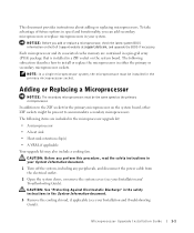
... replace a microprocessor, check the latest system BIOS information on the Dell Support website at support.dell.com, and upgrade the BIOS if necessary.
Each microprocessor and its associated cache memory are contained in a pin-grid array (PGA) package that is installed in a ZIF socket on the system board. The following subsection describes how to install or replace the microprocessor in either...
Microprocessor
Upgrade Installation Guide - Page 4
www.dell.com | support.dell.com
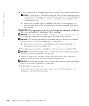
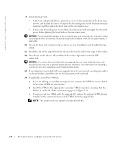
4 If you are upgrading an existing microprocessor, remove the microprocessor heat sink.
NOTE: If a cooling fan is mounted on the heat sink, you can ... microprocessor.
7 Unpack the new microprocessor.
If any of the pins on the microprocessor appear bent, see "Getting Help" in your Installation and Troubleshooting Guide.
1-2
Microprocessor Upgrade Installation Guide
Microprocessor
Upgrade Installation Guide - Page 5
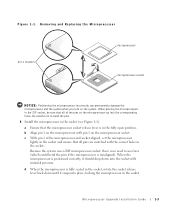
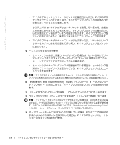
...Align pin 1 on the microprocessor with pin 1 on the microprocessor socket.
c With pin 1 of the microprocessor and socket aligned, set the microprocessor lightly in the socket and ensure that all pins are matched with the correct holes in the socket.
Because the system...lever back down until it snaps into place, locking the microprocessor in the socket.
Microprocessor Upgrade Installation Guide
1-3
Microprocessor
Upgrade Installation Guide - Page 6
....dell.com | support.dell.com
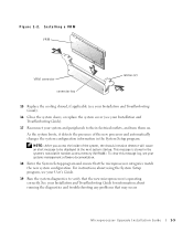
9 Install ...mark on the system board, if applicable.
10 Orient the heat-sink retention clip as shown in your Installation and Troubleshooting Guide.
11 Hook the ... upgrade kit, replace the primary VRM already installed in the system with one of the VRMs from the upgrade kit.
NOTE: The system does not support mismatched VRMs.
1-4
Microprocessor Upgrade Installation Guide
Microprocessor
Upgrade Installation Guide - Page 7
... stored in the system's nonvolatile random-access memory (NVRAM). To clear this message log, see your systems management software documentation.
18 Enter the System Setup program and ensure that the microprocessor categories match the new system configuration. For instructions about using the System Setup program, see your User's Guide.
19 Run the system diagnostics to verify...
Microprocessor
Upgrade Installation Guide - Page 34
www.dell.com | support.dell.com
2 Installation and Troubleshooting Guide
3 Installation and Troubleshooting Guide
4
Installation and Troubleshooting Guide
a
b Installation and Troubleshooting Guide
5 5-1
6
5-2
Microprocessor
Upgrade Installation Guide - Page 35
7
Installation and Troubleshooting Guide
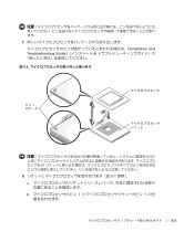
図 5-1
ピン 1
ZIF
8 5-1
a
b 1 1
5-3
Microprocessor
Upgrade Installation Guide - Page 36
www.dell.com | support.dell.com
c 1
ZIF
d
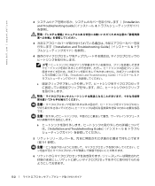
9
10 『Installation and Troubleshooting Guide
11
12 ZIF
Installation and Troubleshooting Guide
13
5-4
Information
Update — 1-GB 512-Mb Memory Modules - Page 1
www.dell.com | support.dell.com
About Cautions
CAUTION: A CAUTION indicates a potential for property damage, personal injury, or death.
Information Update - 1-GB 512-Mb Memory Modules
CAUTION: See your Product Information Guide or System Information Guide for complete information about safety precautions, working inside the computer, and protecting against electrostatic discharge. The industry is...
Information
Update - Page 3

This document provides updated information about the following topics for your system: • Installing the SCSI cable strain-relief bracket • System board connectors for memory modules • Expansion card installation guidelines • Installing the SCSI backplane daughter card • Broadcom NetXtreme Gigabit Ethernet Server Adapter • Microprocessor features • System ...
Information
Update - Page 4
www.dell.com | support.dell.com
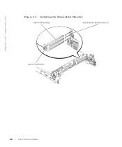
Figure 1-1. Installing the Strain-Relief Bracket
strain-relief bracket
matching rail bracket holes (3)
captive thumbscrew
1-2
Information Update
Information
Update - Page 5
... Modules
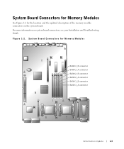
See Figure 1-2 for the location and the updated description of the memory module connectors on the system board. For more information on system board connectors, see your Installation and Troubleshooting Guide. Figure 1-2. System Board Connectors for Memory Modules
BANK3_B connector BANK3_A connector BANK2_B connector BANK2_A connector BANK1_B connector BANK1_A connector
Information...
Information
Update - Page 6
.... For more information on installing the SCSI backplane daughter card, see your Installation and Troubleshooting Guide.
Broadcom NetXtreme Gigabit Ethernet Server Adapter
When a Broadcom NetXtreme Gigabit Ethernet Server Adapter is installed and wake on LAN (WOL) is enabled, your system's connection speed is 10/100-Mbps. The Broadcom NetXtreme Gigabit Server Adapter only supports 10/100-Mbps links...
Information
Update - Page 8
... System Setup program, see your User's Guide.
To enable the Redundant Memory option in the System Setup program, all memory slots in the system must be populated, and all memory modules must be of the same type and size.
The redundant memory options vary according to the number of populated memory banks and whether identical memory modules are installed in...
Rack
Installation Guide - Page 25
... following tools and supplies to install the system in a two-post open-frame relay rack: • #2 Phillips screwdriver • 11/32-inch wrench or nut driver (if changing to a flush...One pair of slide assemblies (two-post) • One stiffening bracket • One cable-management arm • One status indicator cable • Twelve 12-24 x 0.5-inch pan-head Phillips screws • Tie-wraps ...
Rack
Installation Guide - Page 30
....dell.com | support.dell.com
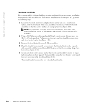
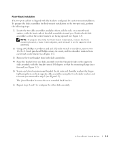
Flush-Mount Installation
The two-post rack kit is shipped with the brackets configured for center-mount installation. To prepare the slide assemblies for flush-mount installation in...slide assembly.
2 Using a #2 Phillips screwdriver and an 11/32-inch wrench or nut driver, remove two 12-24 x 0.5-inch pan-head Phillips screws, two nuts, and two ...
Rack Installation Guide
Rack
Installation Guide - Page 31
... Figure 1-17).
9 Perform steps 7 and 8 to install the right slide assembly in the rack.
10 Use an 11/32-inch wrench or nut driver to fully tighten the nuts on the mounting brackets on ... Install the stiffening bracket between the back ends of the slide assemblies and secure the bracket with a 12-24 0.5-inch pan-head Phillips screw on each slide assembly (see Figure 1-17).
Rack Installation Guide...
2-Post
Rack Installation - Page 7
... and personal injury to yourself and to others may result.
See "CAUTION: Safety Instructions" at the front of this document for additional safety information regarding rack installation.
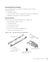
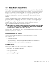
Recommended Tools and Supplies
You need the following tools and supplies to install the system in a two-post open-frame relay rack:
• #2 Phillips screwdriver
•...
2-Post
Rack Installation - Page 13
... center brackets are facing upward (see Figure 1-5).
NOTE: To prepare the slides for flush-mount installation, remove the front mounting bracket, rotate it 180 degrees, and reinstall it on the opposite slide... assembly.
2 Using a #2 Phillips screwdriver and an 11/32-inch wrench or nut driver, remove two 12-24 x 0.5-inch pan-head Phillips screws, two nuts, and two shoulder washers ...
2-Post
Rack Installation - Page 14
www.dell.com | support.dell.com
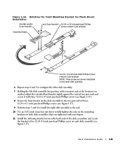
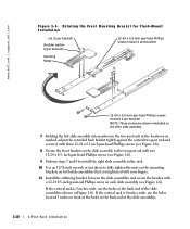
Figure 1-5. Rotating the Front Mounting Bracket for Flush-Mount Installation
nut (2 per bracket)
shoulder washer (2 per bracket)
12-24 x 0.5-inch pan-head Phillips screws (install 2 per bracket)
mounting ...
9 Perform steps 7 and 8 to install the right slide assembly in the rack.
10 Use an 11/32-inch wrench or nut driver to fully tighten the nuts on the mounting...