Gigabyte GS-R1161-RH driver and firmware
Drivers and firmware downloads for this Gigabyte item

Related Gigabyte GS-R1161-RH Manual Pages
Download the free PDF manual for Gigabyte GS-R1161-RH and other Gigabyte manuals at ManualOwl.com
Manual - Page 2

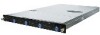
GS-R1161-RH Rack Mount Server
Table of Content
Safety, Care and Regulatory Information 4 Introduction 8 Contents Packages 8 Chapter 1 Features Summary 9 Chapter 2 System Hardware Installation 11
Step 2-1: Chassis Removal and Installation 11 Step 2-2: CPU Installation 12 Step 2-3: Heat Sink Installation 13 Step 2-4: Memory Installation 14 Step 2-5: PCI Expansion Card Installation 15 Step ...
Manual - Page 5

... of fire, use only No. 26 AWG or larger telecommunications line cord. * Do not plug a modem or telephone cable into the network interface controller (NIC) receptacle. * Disconnect the modem cable before opening a product enclosure, touching or installing internal components, or touching an uninsulated modem cable or jack. * Do not use a telephone line to report a gas leak while you are...
Manual - Page 6

GS-R1161-RH Rack Mount Server
Your telephone company may make changes in its facilities, equipment, operations, or procedures that could affect proper operation of your equipment. If they do, you will be notified in advance to give you an opportunity to maintain uninterrupted telephone service. The FCC prohibits this equipment to be connected to...
Manual - Page 8

... is missing or damaged in the
system, please contact your vendor immediately.
; Chassis
;
; Power Supply (Installed)
;
; CPU Heat Sink x 1
;
; Case Handle Kit x 2
; GS-R1161-RH Quick Refernece Guide
; Driver CD for motherboard driver & utility
GA-5YXS2-RH Motherboard (Installed) FAN Duct x 1 Cables (RJ45)
* The items listed above are for reference only, and are subject to change...
Manual - Page 9

...-on card y ICH9R y Supports LSI Software SW RAID 0/1/10 (Windows only) y 5 X System Fan
y Intel® 82566DC & 82573VGbE controllers
y XGI Volari Z9s y 32MB DDR2 y 4 x Hot-Swap SATA HDDs
y ITE IT8718F Super I/O y 1 x Serial port (COM) y 4 x USB 2.0 dual-port connector (2 at front panel) y 1 x VGA connector y 2 x RJ45 LAN ports y P/S 2 Keyboard and Mouse Connectors
y Phoenix BIOS on 8Mb flash ROM...
Manual - Page 11

... in chapter "Important Safety Information" Do not expose the server to extreme environmental conditions. Protect it from dust, humidity, and heat.
Step 2-1: Chassis Removal and Installation
Step 1 Push down the indentation located at two sides of the chassis. Step 2 Slide toward the top chassis cover. Step 3 Lift up to remove the...
Manual - Page 12

GS-R1161-RH Rack Mount Server
Step 2-2: CPU Installation
Please make sure the CPU type and speed that are supported by the motherboard. Step 1 Raise the metal locking lever on the socket. Insert the CPU with the correct orientation. Step 2 The CPU only fits in one orientation. Step 3 Push the metal lever back into locked position.
1 2
3
12
Manual - Page 13

Step 2-3: Heat Sink Installation
Hardware Installation Process
Step 1 Place the Heat Sink on the CPU. Before putting the heat sink on the CPU, please well remember to apply the thermal conductivity compound on the CPU.
Step 2 Seat the heat sink in the retention modules with the four screws. Installation completed.
2 2
2 2
1
13
Manual - Page 14

GS-R1161-RH Rack Mount Server
Step 2-4: Memory Installation
Step 1. Insert the DIMM memory module vertically into the DIMM slot, and push it down. Step 2. Close the plastic clip at both edges of the DIMM slots to lock the ...
Manual - Page 15

GS-R1161-RH Rack Mount Server
Step 2-5: PCI Expansion Card Installation
GS-R1161-RH provides expansion riser slots for one PCI-E x8 slot; and one with PCI-E x8 slot (at x1 bandwidth). To install the peripheral, please go through the following steps. Note!! Before installing the expansion card, please check the card size limitation. Size limitation for standard riser card is 182mm; and the size ...
Manual - Page 16

Hardware Installation Process
Step 2-6: Hard Disk Drive Installation
Step 1 Press the release button. Step 2 Pull the blank out of the drive bay. Step 3 Slide hard disk into blank. Step 4 Secure it with screws. Step 5 Slide the blank into the bay until it locks into place. Connect cable and power.
1
2 3 4 4
4 4
16
Manual - Page 17

Hardware Installation Process
Step 2-7: FAN Duct Removal and Installation
Step 1 Align the fan duct with the guiding groove. Push down the fan duct into system ntil the its firmly seats.
Guiding groove
17