Gigabyte GS-R22PD1 driver and firmware


Related Gigabyte GS-R22PD1 Manual Pages
Download the free PDF manual for Gigabyte GS-R22PD1 and other Gigabyte manuals at ManualOwl.com
Manual - Page 2

... of this manual may be reproduced, copied, translated, transmitted, or published in any form or by any means without GIGABYTE's prior written permission.
Documentation Classifications In order to assist in the use of this product, GIGABYTE provides the following types of documentations:
For quick set-up of the product, read the Quick Installation Guide included with...
Manual - Page 4

... 13 2-1 Removing Chassis Cover 14 2-2 Installing the CPU 15 2-3 Installing the Heat Sink 16 2-4 Installing the Memory 17
2-4-1 Dual/3 Channel Memory Configuration 17 2-4-2 Installing a Memory 18 2-5 Installing the PCI Expansion Card 19 2-6 Installing the Hard Disk Drive 20 2-7 Replacing the Motherboard Tray 21 2-8 Replacing the Power Supply 22
Chapter 3 System Appearance 23 3-1 Front...
Manual - Page 6
Box Contents
GS-R22PD Driver CD
• The box contents above are for reference only and the actual items shall depend on the product package you obtain. The box contents are subject to change without notice.
• The motherboard image is for reference only.
- 6 -
Manual - Page 7

...; To avoid electrical shock, always unplug all power cables and modem cables from the wall outletsbefore removing covers. • Allow the product to cool before removing covers or touching internal components.
Precaution for Product with Laser Devices Observe the following precautions for laser devices: • Do not open the CD-ROM drive, make adjustments, or perform procedures on...
Manual - Page 8

... limits for a Class A digital device,pursuant to Part 15 of the FCC Rules. These limits are designed to provide reasonable protection againstharmful interference when the equipment is operated in a commercial environment. This equipmentgenerates, uses, and can radiate radio frequency energy and, if not installed and used in accordance withthe instruction manual, may cause harmful interference...
Manual - Page 9
... power utility...Load Number (LN) assigned to each terminal device denotes the...digital device pursuantPart 15 of the FCC Rules. These limits are designed to provide reasonable protection againstharmful interference when the equipment is operated in a commercial environment. This equipmentgenerate, uses, and can radiate radio frequency energy, and if not installed and used in accordancewith the instructions...
Manual - Page 10
... read the service guide and follow these procedures:
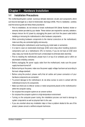
• Prior to installation, do not remove or break motherboard S/N (Serial Number) sticker or warranty sticker provided by your dealer. These stickers are required for warranty validation.
• Always remove the AC power by unplugging the power cord from the power outlet before installing or removing the motherboard or other hardware...
Manual - Page 11
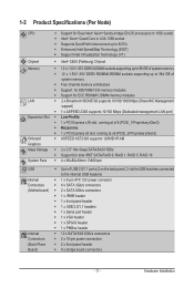
...x 3.5" Hot-Swap SATA/SAS HDDs ŠŠ Support for Intel IRST SATA RAID 0, RAID 1, RAID 5, RAID 10 ŠŠ 4 x 80x80x38mm 13800rpm
USB Internal Connectors (Motherboard)
Internal Connectors (Back Plane Board)
ŠŠ Up to 4 USB 2.0/1.1 ports (2 on the back panel, 2 via the USB brackets connected to the internal USB headers)
ŠŠ 1 x 9-pin ATX 12V power connector ŠŠ...
Manual - Page 12

... Management LAN port ŠŠ 1 x COM port ŠŠ 1 x VGA port ŠŠ 1 x Power button ŠŠ 1 x ID Switch button ŠŠ 1 x NMI button ŠŠ 1 x BMC reset button ŠŠ 1 x Power status LED ŠŠ 1 x Power button/LED ŠŠ 1 x ID button/LED
BMC Controller ŠŠ ASPEED AST2300 with 128Mb SPI flash
Hardware Monitor
BIOS Environment...
Manual - Page 13

... the CPU specifications. It is not recommended
that the system bus frequency be set beyond hardware specifications since it does not meet the standard requirements for the peripherals. If you wish to set the frequency beyond the standard specifications, please do so according to your hardware specifications including the CPU, graphics card, memory, hard drive, etc.
- 13 -
Hardware Installation
Manual - Page 14

2-1 Removing Chassis Cover
Before you remove or install the system cover • Make sure the system is not turned on or connected to AC power.
Follow these instructions to remove the system cover:
1. Loosen and remove the screws securing the front and back cover. 2. Holding both sides of middle top cover and vertically ...
Manual - Page 15

... motherboard supports the CPU. • Always turn off the computer and unplug the power cord from the power outlet before installing
the CPU to prevent hardware damage. • Unplug all cables from the power outlets. • Disconnect all telecommunication cables from their ports. • Place the system unit on a flat and stable surface. • Open the system according to the instructions...
Manual - Page 16

... Sink
Follow these instructions to install the heat sinks:
1. Apply thermal compound evenly on the top of the CPU. 2. Remove the protective cover from the underside of the heat sink. 3. Place the heat sink(s) on top of the CPU and tighten the four positioning screws.
2
2
1
CPU0 and CPU1 use the different CPU heat sinks. Please...
Manual - Page 17
... you begin to install the memory:
• Make sure that the motherboard supports the memory. It is recommended that memory of the
same capacity, brand, speed, and chips be used.•
Always turn off the computer and
unplug the power cord from the power outlet before installing the memory to prevent hardware
damage.
• Memory modules have a foolproof design. A memory module can be...
Manual - Page 18
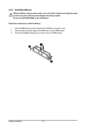
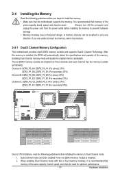
2-4-2 Installing a Memory
Before installing a memory module, make sure to turn off the computer and unplug the power cord from the power outlet to prevent damage to the memory module. Be sure to install DDR3 DIMMs on this motherboard. Follow these instructions to install the Memory: 1. Insert the DIMM memory module vertically into the DIMM slot, and push it down. 2. Close the plastic clip at both...
Manual - Page 19

... could result in personal injury or damage to equipment.
• The PCI riser assembly does not include a riser card or any cabling as standard. To install a PCI card, a riser card must be installed.
Follow these instructions to PCI Expansion card:
1. Loosen the riser bracket securing screws from the side of motherboard tray. 2. Loosen the riser bracket screw. 3. Lift the riser bracket slightly...
Manual - Page 20

... you begin to install the Hard disk drive: • Take note of the drive tray orientation before sliding it out. • The tray will not fit back into the bay if inserted incorrectly. • Make sure that the HDD is connected to the HDD connector on the backplane.
Follow these instructions to Hard disk drive:
1. Press the...
Manual - Page 21

2-7 Replacing the Motherboard Tray
Follow these instructions to replace the motherboard tray:
1. Remove the chassis cover. See Removing the Chassis Cover on page 14. 2. Disconnect the power, SATA, front panel, and mainboard cable connectors. 3. Pull up the tray handle and side of the motherboard tray along the direction of the arrow.
- 21 -
Hardware Installation
Manual - Page 22
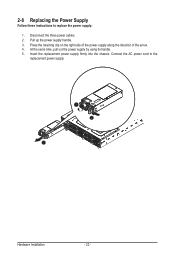
2-8 Replacing the Power Supply
Follow these instructions to replace the power supply: 1. Disconnect the three power cables. 2. Pull up the power supply handle. 3. Press the retaining clip on the right side of the power supply along the direction of the arrow. 4. At the same time, pull out the power supply by using its handle. 5. Insert the replacement power supply firmly...
Manual - Page 39

... its four processing cores to improve performance with applications that are not multi-threaded or optimized for quad-core processors. Options available: Enabled/Disabled. Default setting is Enabled.
(Note) This item is present only if you install a CPU that supports this feature. For more information about
Intel CPUs' unique features, please visit Intel's website.
BIOS Setup
- 39 -