Lexmark WinWriter 100 driver and firmware
Drivers and firmware downloads for this Lexmark item

Related Lexmark WinWriter 100 Manual Pages
Download the free PDF manual for Lexmark WinWriter 100 and other Lexmark manuals at ManualOwl.com
Service Manual - Page 2

... inaccuracies or typographical errors. Changes are periodically...LEXMARK INTERNATIONAL, INC. 1993. ALL RIGHTS RESERVED.
UNITED STATES GOVERNMENT RESTRICTED RIGHTS This software and documentation are provided with RESTRICTED RIGHTS. Use, duplication or disclosure by the Government is subject to restrictions as set forth in subparagraph (c)(1)(ii) of the Rights in Technical Data and Computer Software...
Service Manual - Page 6

... in your country.
Federal Communications Commission (FCC) Statement
This printer has been tested and found to comply with the limits for a Class B digital device, pursuant to Part 15 of the FCC Rules. These limits are designed to provide reasonable protection against harmful interference in a residential installation. This equipment generates, uses, and can radiate radio...
Service Manual - Page 9
... in the United States and/or other countries, and are used under license:
IBM
Except for archiving, Apple software shall not be copied onto another disk or into memory unless as part of the execution of the IBM Printer Utilities.
Preface
This manual is divided into the following chapters:
1. "General Information" contains a general description of the...
Service Manual - Page 22
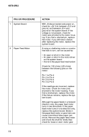
...Board
2 Paper Feed Motor
ACTION
With J5 disconnected and power on, check for +24 V dc between J5-3 and ground, and between J5-4 and ground on the system board...open or short in the motor driver
on the system board • A bind in the paper feed mechanism
Check for 100 ohms (±20 ohms) between... board. Binds in the paper feed motor or gear train can cause intermittent false paper jam errors....
Service Manual - Page 29
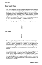
... The test begins when the power button is pressed. Except for adjusting the bi-directional alignment, the printer does not need to be ... Page
J12
This test prints a test page followed by a shortened version of the test page. The first line is the code level and...Install the printer on a PC and run the bi-directional alignment adjustment procedure on the service manual diskette.
Diagnostic Aids 18
Service Manual - Page 30
... the flashing power on light and indicates the type of error indication. Additional pages print the same as the first page without the purge pattern.
Parallel Port Test
J12
This test requires a parallel port wrap plug. Install the wrap plug in the parallel port before you start the test. This test performs a wraparound test between the printer parallel port...
Service Manual - Page 32
... to make adjustments to the printer and how to remove defective ...ESD-sensitive parts, follow the instructions below in addition to all the usual precautions, such as turning off power before removing logic boards:
• Keep the ESD...• Prevent ESD-sensitive parts from being accidentally touched by
other personnel. Install machine covers when you are not working on the machine, and do not ...
Service Manual - Page 39
... the carrier clears the encoder strip. Place the carrier on top of the paper guide. 5. Remove the encoder strip from the left mounting peg. To do this, ...cable connectors at the system board and
disconnect the cables. 4. Disconnect connectors J4, J5, and J6 from the system board. 5.
Remove the machine from the base. To do this, unlatch the 4 base frame latches. Lift the machine from the base and set...
Service Manual - Page 41
... the carrier guide.
To install the left side frame onto the middle frame, align the right side frame latch with the latching surface on the middle frame before you align the roller shafts and carrier guide. It may be easier to do this with the machine on its right side.
Maintenance Drive And Rocker...
Service Manual - Page 44
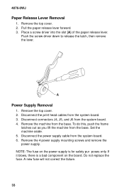
... this, push the frame
latches out as you lift the machine from the base. Set the machine aside. 5. Disconnect the power supply cable from the system board. 6. Remove the 4 power supply mounting screws and remove the power supply. NOTE: The fuse on the power supply is for safety pur- poses only. If it blows, there is a bad...
Service Manual - Page 46
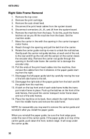
... the auto sheet feed. 4. Disconnect the print head cables from the system board. 5. Disconnect connectors J4, J5, and J6 from the system board. 6. Remove the machine from the base. To do this, push the frame
latches out as you lift the machine from the base. Set the machine aside. 7. Move the carrier in line...
Service Manual - Page 47
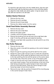
...install the right side frame onto the middle frame, align the right side frame latch with the latching surface on the mid frame before you align the roller shafts and carrier guide... Remove the print head cable. 4. Remove the rubber backer from the carrier.
Small Feed Roller Assembly Removal
1. Remove the top cover. 2. Remove the auto sheet feed. 3. Remove the paper guide 4. Carefully remove the ...