MSI PM104 driver and firmware


Related MSI PM104 Manual Pages
Download the free PDF manual for MSI PM104 and other MSI manuals at ManualOwl.com
User Guide - Page 2
...
Technical Support
If a problem arises with your system and no solution can be obtained from the user's manual, please contact your place of purchase or local distributor. Alternatively, please try the following help resources for further guidance.
Visit the MSI website at http://global.msi.com.tw/index.php? func=service for FAQ, technical guide, BIOS updates, driver updates, and...
User Guide - Page 4

... for a class A digital device, pursuant to part 15 of the FCC rules. These limits are designed to provide reasonable protection against harmful interference when the equipment is operated in a commercial environment. This equipment generates, uses and can radiate radio frequency energy and, if not installed and used in accordance with the instruction manual, may cause...
User Guide - Page 8

... ...2-6 Connector ...2-7 Jumper ...2-12 Slot ...2-13 System Assembly Flowchart 2-15 System Assembly 2-16 Rack Mounting ...2-26 Chapter 3 BIOS Setup 3-1 Entering Setup ...3-2 The Menu Bar ...3-4 Main ...3-5 Advanc ed ...3-6 Boot ...3-19 Security ...3-23 Chipset ...3-24 Exit ...3-26 Appendix A Intel ICH9M-E SATA RAID A-1 Introduction ...A-2 BIOS Configuration A-3 Installing Driver ...A-9
viii
User Guide - Page 17
Hardware Setup
Chapter 2
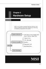
Hardware Setup
Refer to the system assembly flowchart and the chart below to determine the proper sequence of removing or installing components to the server.
Mainboard Hardware
System Assembly MS-92B9
CPU, Memory, Power Supply, Back Panel, Connector, Jumper, Slot Chassis Cover CPU, Heatsink Memory Expansion Card Hard Disk Drive
Rack Mounting
2-1
User Guide - Page 19
Hardware Setup
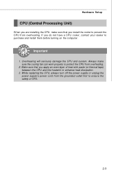
CPU (Central Processing Unit)
W hen you are installing the CPU, make sure that you install the cooler to prevent the CPU from overheating. If you do not have a CPU cooler, contact your dealer to purchase and install them before turning on the computer.
Important
1. Overheating will seriously damage the CPU and system. Always make sure the cooling fan can...
User Guide - Page 20

....
DDR2
240-pin, 1.8V
64x2=128 pin
56x2=112 pin
Installing Memory Modules
1. Locate the DIMM slots on the mainboard. Flip open the retaining clip at each side of the DIMM ...
Important
You can barely see the golden finger if the DIMM is properly inserted in the DIMM slot.
3. Manually check if the DIMM has been locked in place by the retaining clips at the sides.
4. Follow the same procedures to...
User Guide - Page 23

... warning, you must enter the BIOS utility and clear the record.
JCASE1
CINTRU
GND
12
IDE Connector: IDE1
This connector supports IDE hard disk drives, optical disk drives and other IDE devices.
IDE1
Important
If you install two IDE devices on the same cable, you must configure the drives separately to master / slave mode by setting jumpers. Refer to IDE device's documentation supplied by the...
User Guide - Page 29
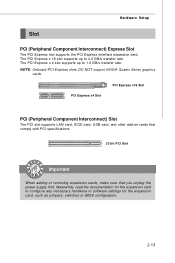
... PCI slot supports LAN card, SCSI card, USB card, and other add-on cards that comply with PCI specifications.
32-bit PCI Slot
Important
When adding or removing expansion cards, make sure that you unplug the power supply first. Meanwhile, read the documentation for the expansion card to configure any necessary hardware or software settings for the expansion card, such as jumpers, switches or BIOS...
User Guide - Page 31
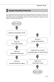
... wear anti-static gloves when handling electrical components and exercise caution during the installation process. For more information, contact your local dealer or experienced technician.
START
REMOVE CHASSIS COVER
INSTALL CPU & HEATSINK
INSTALL HARD DISK DRIVES
INSTALL MEMORY MODULES
CHECK IF ALL PARTS ARE PROPERLY CONNECTED
INSTALL PCI EXPANSION CARDS
REPLACE CHASSIS COVER
FINISH
2-15
User Guide - Page 33
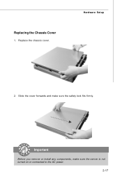
Replacing the Chassis Cover
1. Replace the chassis cover.
Hardware Setup
2. Slide the cover forwards and make sure the safety lock fits firmly.
Important
Before you remove or install any components, make sure the server is not turned on or connected to the AC power.
2-17
User Guide - Page 34
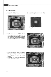
... form of a screw head. Make sure that you deactuate this mechanism with a screwdriver before installing the CPU.
4. Place the CPU on top of the socket. Make sure to align the gold arrow on the CPU with the arrow key on the socket.
5. Push the CPU down until its pins securely fit into the socket.
2-18
User Guide - Page 35
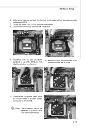
...) on top of the CPU and fit it into the retention mechanism.
10. Press the clips into the hooks to secure the cooler set in place.
11. Connect the fan power cable from the mounted fan to the fan power connector on the board.
Note: The cooler set has to be installed to prevent the CPU from overheating.
2-19
User Guide - Page 36
MS-92B9 Server
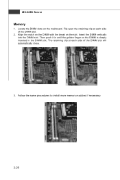
Memory
1. Locate the DIMM slots on the mainboard. Flip open the retaining clip at each side of the DIMM slot.
2. Align the notch on the DIMM ... is deeply inserted in the DIMM slot. The retaining clip at each side of the DIMM slot will automatically close.
3. Follow the same procedures to install more memory modules if necessary.
2-20
User Guide - Page 39
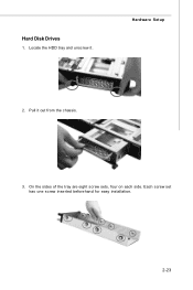
Hard Disk Drives
1. Locate the HDD tray and unscrew it.
Hardware Setup
2. Pull it out from the chassis.
3. On the sides of the tray are eight screw sets, four on each side. Each screw set has one screw inserted beforehand for easy installation.
2-23
User Guide - Page 40
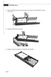
MS-92B9 Server 4. Place the HDD into the tray and align the screw holes on the HDD with the ones
on the tray.
5. Srew the HDD firmly to the tray.
6. Follow the same procedures to install the second HDD.
2-24
User Guide - Page 48
... 1st line appearing after the memory count is the BIOS version. It is usually in the format: A92B9IMS V1.0 071508 where: 1st digit refers to BIOS maker as A = AMI, W = AWARD, and P = PHOENIX. 2nd - 5th digit refers to the model number. 6th digit refers to the chipset as I = Intel, N = nVidia, and V = VIA. 7th - 8th digit refers to the customer as...
User Guide - Page 51
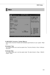
Main
BIOS Setup
AM I BIOS, Processor, System M emory These items show the firmware and hardware specifications of your system. Read only.
System Time This setting allows you to set the system time. The time format is .
System Date This setting allows you to set the system date. The date format is , .
3-5
User Guide - Page 64

MS-92B9 Server USB Configuration
Legacy USB Support Set to [Enabled] if you need to use any USB 1.1/2.0 device in the operating system that does not support or have any USB 1.1/2.0 driver installed, such as DOS and SCO Unix.
USB 2.0 Controller Mode This setting specifies the operation mode of the onboard USB 2.0 controller.
3-18
User Guide - Page 81
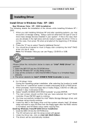
.../DVD or USB) you created in step 3 and press Enter.
6. Select "Intel(R) ICH9M-E SATA RAID Controller" an press ENTER. 7. The next screen should confirm that you have selected the Intel® RAID
controller. Press ENTER again to continue. 8. You have successfully installed the Intel® Matrix Storage Manager driver, and
W indows setup should continue. 9. Leave the disk in the floppy drive until...
User Guide - Page 82

MS-92B9 Server † Confirming Windows Vista/XP/2003 Driver Installation
1. From W indows Vista/XP/2003, open the Control Panel from My Computer followed by the System icon.
2. Choose the Hardware tab, then click the Device M anager tab. 3. Click the "+" in front of the SCSI and RAID Controllers hardware type. The
driver Intel(R) ICH9M -E SATA RAID Controller should appear.
A-10