MSI Pro266TD driver and firmware


Related MSI Pro266TD Manual Pages
Download the free PDF manual for MSI Pro266TD and other MSI manuals at ManualOwl.com
User Manual - Page 2

... for a class B digital device, pursuant to part 15 of the FCC rules. These limits are designed to provide reasonable protection against harmful interference when the equipment is operated in a commercial environment. This equipment generates, uses and can radiate radio frequency energy and, if not installed and used in accordance with the instruction manual, may cause...
User Manual - Page 3

...reserve the right to make changes without notice.
Trademarks All trademarks used in this manual are the property of their respective owners.
Intel and Pentium are registered trademarks ...of IBM Corporation. Windows 98/2000/ME and Windows NT are registered trademarks of Microsoft. Netware is a registered trademark of Novell. Award is a registered trademark of Award Software Inc.
Revision History
...
User Manual - Page 5
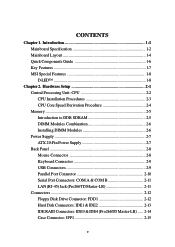
... 2-6 Installing DIMM Modules 2-6 Power Supply 2-7 ATX 20-Pin Power Supply 2-7 Back Panel 2-8 Mouse Connector 2-8 Keyboard Connector 2-9 USB Connectors 2-9 Parallel Port Connector 2-10 Serial Port Connectors: COM A & COM B 2-11 LAN (RJ-45) Jack (Pro266TD Master-LR 2-11 Connectors 2-12 Floppy Disk Drive Connector: FDD1 2-12 Hard Disk Connectors: IDE1 & IDE2 2-13 IDE RAID Connectors...
User Manual - Page 9

... install SINGLE CPU on the board.
Chipset z VIA® VT8653 chipset (552 BGA)
- 100/133MHz FSB settings - AGP 4x and PCI Advanced high performance memory controller z VIA® VT8233 chipset (376 BGA) - High Bandwidth Vlink Client controller - Integrated Fast Ethernet LPC - Ultra DMA 33/66/100 master mode PCI EIDE controller - ACPI z 266MB/sec high bandwidth North/South Bridge V-Link Bus
Clock...
User Manual - Page 13

... Installing power supply
See p. 2-7
IDE1& IDE2
Connecting to IDE hard disk drives
See p. 2-13
IDE3& IDE4
Connecting to IDE RAID hard disk drives See p. 2-14
FDD1
Connecting to floppy disk drive
See p. 2-12
USB2/3
Connecting to USB interfaces
See p. 2-22
PCI Slot 1~5
Installing PCI expansion cards
See p. 2-25
AGP Slot
Installing AGP cards
See p. 2-25
JMDM1
Connecting to modem...
User Manual - Page 15

...
System Power ON - The D-LED will hang here if the processor is damaged or not installed properly. Early Chipset Initialization
Memory Detection Test - Testing onboard memory size. The D-LED will hang if the memory module is damaged or not installed properly. Decompressing BIOS image to RAM for fast booting.
Initializing Keyboard Controller.
Testing VGA BIOS - This will start writing VGA sign...
User Manual - Page 17
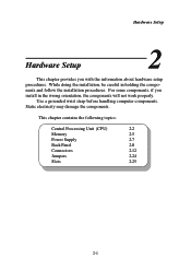
... procedures. For some components, if you install in the wrong orientation, the components will not work properly.
Use a grounded wrist strap before handling computer components. Static electricity may damage the components.
This chapter contains the following topics:
Central Processing Unit (CPU)
2-2
Memory
2-5
Power Supply
2-7
Back Panel
2-8
Connectors
2-12
Jumpers
2-24
Slots...
User Manual - Page 18

Chapter 2
Central Processing Unit: CPU
The mainboard supports Single/Dual Intel® Pentium III processors. The mainboard uses two CPU sockets called Socket 370 for easy CPU installation. You can install SINGLE or DUAL CPUs on the board to meet your own needs. Keep the following points in mind before installing CPU(s):
z If SINGLE CPU is intended, always install the CPU on the CPU1...
User Manual - Page 19
Hardware Setup
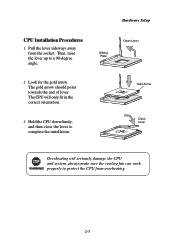
CPU Installation Procedures
1. Pull the lever sideways away from the socket. Then, raise the lever up to a 90-degree angle.
2. Look for the gold arrow. The gold arrow should point towards the end of lever. The CPU will only fit in the correct orientation.
3. Hold the CPU down firmly, and then close the lever...
User Manual - Page 21

Hardware Setup
Memory
The mainboard provides 4 sockets for 184-pin DDR DIMM (Double InLine Memory Module) modules and supports a maximum memory size of 4GB.
DDR DIMM Slots (DIMM 1~4)
Introduction to DDR SDRAM
You can install PC1600/PC2100 DDR SDRAM modules on the DDR DIMM slots (DIMM 1~4).
DDR (Double Data Rate) SDRAM is similar to conventional SDRAM, but...
User Manual - Page 22
Chapter 2
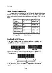
DIMM Modules Combination
At least one DIMM module should be installed on the motherboard. Memory modules can be installed on the slots in any order. The single-/ double-sided memory modules that each DIMM slot supports are listed as below:
Socket
Memory Module
DIMM 1
S/D
(Bank0 & Bank1)
DIMM 2
S/D
(Bank2 & Bank3)
DIMM 3
S/D
(Bank4 & Bank5)
DIMM 4
S/D
(Bank6 & Bank7)
...
User Manual - Page 23
Hardware Setup
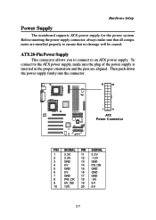
Power Supply
The mainboard supports ATX power supply for the power system. Before inserting the power supply connector, always make sure that all components are installed properly to ensure that no damage will be caused.
ATX 20-Pin Power Supply
This connector allows you to connect to an ATX power supply. To connect to the ATX power supply, make...
User Manual - Page 29

Hardware Setup
Hard Disk Connectors: IDE1 & IDE2
The mainboard uses an IDE controller on the VIA® VT8233 chipset that provides PIO mode 0-4, Bus Master, and Ultra DMA 33/66/100 modes. It has two HDD connectors IDE1 (Primary) and IDE2 (Secondary). You can connect up to four hard disk drives, CD-ROM or 120MB Floppy to IDE1 and...
User Manual - Page 30

... a Master and a Slave drive to each IDE RAID connector. - The two connectors support hard disk drives only. - For more information on IDE RAID, please refer to IDE RAID Manual. (Please note only two of the installed hard disk drives will adopt RAID function, and usually they are Master drives.)
2
40
1
39
IDE4
2
40
1
39
IDE3
If you install two hard disks on cable, you must configure...
User Manual - Page 36
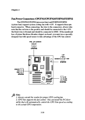
... Hardware Monitor chipset on-board, you must use a specially designed fan with speed sensor to take advantage of the CPU fan control.
GND +12V SENSOR
CPUFN2
+12V
SENSOR
GND
SYSFN1
SENSOR +12V GND
CPUFN1
NC +12V GND
SYSFN2
Note: 1. Always consult the vendor for proper CPU cooling fan. 2. CPU Fan supports the fan control. You can install the PC...
User Manual - Page 51
...174; BIOS Setup
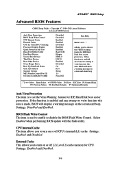
Advanced BIOS Features
CMOS Setup Utility - Copyright (C) 1984-2001 Award Software Advanced BIOS Features
Anti-Virus Protection BIOS Flash Write Control CPU Internal Cache External Cache CPU L2 Cache ECC Checking Processor Number Feature Quick Power On Self Test Raid & SCSI Boot Order First Boot Device Second Boot Device Third Boot Device Boot Other Device Swap Floppy Drive Boot...
User Manual - Page 61
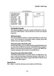
... drive access. Set to Disabled if your primary and/or secondary add-in IDE interface does not support prefetching.
Primary/Secondary Master/Slave PIO The four fields allow you to set a PIO (Programmed Input/Output) mode for each of the four IDE devices that the onboard IDE interface supports. Modes 0~4 provide increased performance. In Auto mode, BIOS...
User Manual - Page 64

...or ECP+EPP mode.
Init Display First This item specifies which VGA card is your primary graphics adapter. Available settings: PCI Slot and AGP.
OnChip USB Controller The item specifies which USB (Universal Serial Bus) Port is enabled. Settings: All Disabled, ALL Enabled, 2&3 USB Port, 1&2 USB Port, 1&3 USB Port, 3 USB Port, 2 USB Port, 1 USB Port.
USB Keyboard Support Set to Enabled if your need...
User Manual - Page 66
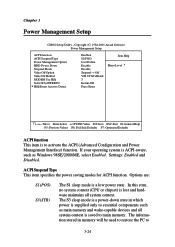
... is ACPI-aware, such as Windows 98SE/2000/ME, select Enabled. Settings: Enabled and Disabled.
ACPI Suspend Type This item specifies the power saving modes for ACPI function. Options are:
S1(POS) S3(STR)
The S1 sleep mode is a low power state. In this state, no system context (CPU or chipset) is lost and hardware maintains...
User Manual - Page 71
AWARD® BIOS Setup
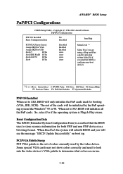
PnP/PCI Configurations
CMOS Setup Utility - Copyright (C) 1984-2001 Award Software PnP/PCI Configurations
PNP OS Installed Reset Configuration Data
No Disabled
Item Help
PCI/VGA Palette Snoop
Assign IRQ For VGA
Assign IRQ For USB
Slot1/5
INTA
Slot2/IDE RAID INTA
Slot3/i82559 INTA
Slot4
INTA
Disabled Enabled Enabled Auto Auto Auto Auto
Menu Level 8
Select Yes ...