MSI Keeper driver and firmware


Related MSI Keeper Manual Pages
Download the free PDF manual for MSI Keeper and other MSI manuals at ManualOwl.com
User Guide - Page 2
...
Technical Support
If a problem arises with your system and no solution can be obtained from the user's manual, please contact your place of purchase or local distributor. Alternatively, please try the following help resources for further guidance.
Visit the MSI website at http://global.msi.com.tw/index.php? func=service for FAQ, technical guide, BIOS updates, driver updates, and...
User Guide - Page 4
...
T h is eq uip men t h as been tested and found to comply with the limits for a Class B digital device, pursuant to Part 15 of the FCC Rules. These limits are designed to provide reasonable protection against harmful interference in a residential installation. This equipment generates, uses and can radiate radio frequency energy and, if not...
User Guide - Page 13
... chapter provides you with the information about hardware setup procedures. While doing the installation, be careful in holding the components and follow the installation procedures. For some components, if you install in the wrong orientation, the components will not work properly. Use a grounded wrist strap before handling computer components. Static electricity may damage the components...
User Guide - Page 15
... Setup
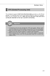
CPU (Central Processing Unit)
The mainboard supports Intel® Core Duo/Core Solo processor in the 478 pin package. The mainboard uses a CPU socket called mPGA478 for easy CPU installation. W hen you are installing the CPU, make sure the CPU has a heat sink and a cooling fan attached on the top to prevent overheating.
Important
1. Overheating will seriously damage the CPU...
User Guide - Page 16
MS-9641 Mainboard
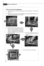
CPU & Cooler Set Installation
1. Loose the screw on the CPU socket with a tank screwdriver in clockwise direction.
2. Place the CPU on top of the socket. Make sure to align the gold arrow on the CPU with the arrow key on the socket.
4. On the front end of the CPU socket is a
locking mechanism designed into...
User Guide - Page 18
....
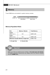
DDR2
240-pin, 1.8V
64x2=128 pin
56x2=112 pin
Memory Population Rules
Slot
Memory Module
DIMM 0
(Bank 0 & 1)
S/D
DIMM 1
(Bank 2 & 3)
S/D
Maximum System Memory Supported
Total Memory
128MB~2GB 128MB~2GB 128MB~4GB
S: Single Side
D: Double Side
Important
- Make sure that you install memory modules of the same type and density. - To enable successful system boot-up, always...
User Guide - Page 19
Hardware Setup
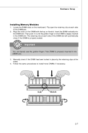
Installing Memory Modules
1. Locate the DIMM slots on the mainboard. Flip open the retaining clip at each side of the DIMM slot.
2. Align the... is properly seated.
Important
You can barely see the golden finger if the DIMM is properly inserted in the DIMM slot.
3. Manually check if the DIMM has been locked in place by the retaining clips at the sides.
4. Follow the same procedures to...
User Guide - Page 20
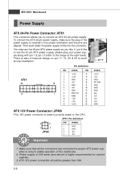
...power supply, please plug your power supply along with pin 1 & pin 13 (refer to the image at the right hand). There is also a foolproof design on pin 11, 12, 23 & 24 to avoid wrong installation... GND PS-ON# GND GND GND Res +5V +5V +5V GND
ATX 12V Power Connector: JPW0
This 12V power connector is used to provide power to the CPU.
JPW1 Pin Definition
3
4
1
2
JPW0
PIN
SIGNAL
1
GND
2
GND
3...
User Guide - Page 23
Hardware Setup
Connectors
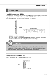
Hard Disk Connector: IDEB0
The mainboard provides a one-channel Ultra ATA 100 bus Master IDE controller that supports PIO mode 0~4, Bus Master, and Ultra DMA 66/100 function. You can connect hard disk drives, CD-ROM drives and other IDE devices.
IDEB0
IDE 1
IDE1 Definition
UDMA 66/100
Controller Intel ICH7/ICH7R
RAID ATAPI N/A Yes
IDEB0 (Primary IDE Connector) IDE1 ...
User Guide - Page 38
...
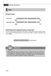
BOTTOM View
A94
A1
PCI (Peripheral Component Interconnect) Slot
The PCI slots support LAN cards, SCSI cards, USB cards, and other add-on cards that comply with PCI specifications. At 32 bits and 33 MHz, it yields a throughput rate of 133 MBps.
32-bit PCI Slot
Important
When adding or removing expansion cards, make sure that you unplug the power supply first. Meanwhile, read...
User Guide - Page 40
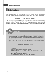
... 1st line appearing after the memory count is the BIOS version. It is usually in the format: P9641IMS V2.0 031908 where: 1st digit refers to BIOS maker as A = AMI, W = AWARD, and P = PHOENIX. 2nd - 5th digit refers to the model number. 6th digit refers to the chipset as I = Intel, N = nVidia, and V = VIA. 7th - 8th digit refers to the customer as...
User Guide - Page 47
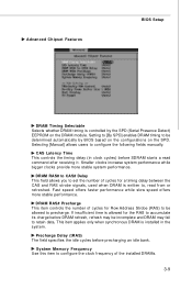
Advanced Chipset Features
BIOS Setup
DRAM Timing Selectable Selects whether DRAM timing is controlled by the SPD (Serial Presence Detect) EEPROM on the DRAM module. Setting to [By SPD] enables DRAM timing to be determined automatically by BIOS based on the configurations on the SPD. Selecting [Manual] allows users to configure the following fields manually.
CAS Latency Time This controls the...
User Guide - Page 48
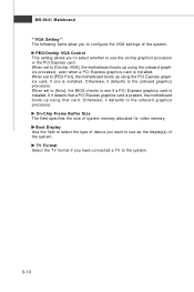
... configure the VGA settings of the system.
PEG/Onchip VGA Control This setting allows you to select whether to use the onchip graphics processor or the PCI Express card. W hen set to [Onchip VGA], the motherboard boots up using the onboard graphics processor, even when a PCI Express graphics card is installed. When set to [PEG Port], the motherboard boots up using the PCI Express graphics card, if...
User Guide - Page 50
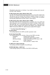
...party IDE bus master driver). If your hard drive and your system software both support Ultra DMA/33, Ultra DMA/66, Ultra DMA/100 and Ultra DMA/133, select [Auto] to enable BIOS support.
*** On-Chip Serial ATA Setting ***
SATA Mode This setting specifies the SATA controller operation mode.
On-Chip Serial ATA
This setting specifies the function of the on-chip SATA controller.
[Disabled]
Disable...
User Guide - Page 51
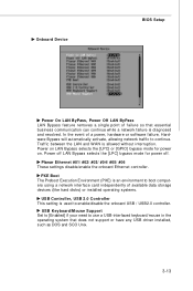
...the onboard Ethernet controller.
PXE Boot The Preboot Execution Environment (PXE) is an environment to boot computers using a network interface card independently of available data storage devices (like hard disks) or installed operating systems.
USB Controller, USB 2.0 Controller This setting is used to enable/disable the onboard USB / USB2.0 controller.
USB Keyboard/Mouse Support Set to [Enabled...
User Guide - Page 52
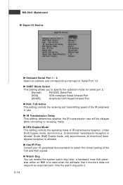
MS-9641 Mainboard Super IO Device
Onboard Serial Port 1 / 2 Select an address and corresponding interrupt for Serial Port 1/2.
UART M ode Select
This setting allows you to specify the operation mode for serial port 2.
[Normal]
RS-232C Serial Port
[IrDA]
IrDA-compliant Serial Infrared Port
[ASKIR]
Amplitude Shift Keyed Infrared Port
RxD, TxD Active This setting controls the receiving and ...