Sony PCV-RX462DS - VAIO - 128 MB RAM driver and firmware
Related Sony PCV-RX462DS Manual Pages
Download the free PDF manual for Sony PCV-RX462DS and other Sony manuals at ManualOwl.com
System Reference Manual - Page 2
... or registered trademarks of their respective owners.
Owner's Record
The model number and serial number are located on the back of your VAIO® computer. Record the serial number in the space provided here. Refer to the model and serial number when you call your Sony Service Center.
Model Numbers: PCV-RX462DS/ PCV-RX463DS/PCV-RX465DS/ PCV-RX470DS/PCV-RX480DS/ PCV-RX490TV
Serial Number
ii
System Reference Manual - Page 3
... nm (CD)
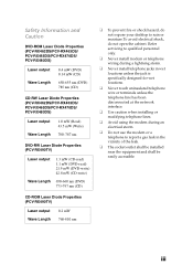
CD-ROM Laser Diode Properties (PCV-RX490TV)
Laser output Wave Length
0.2 mW 760-810 nm
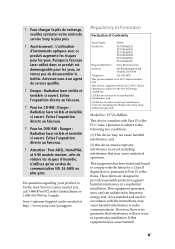
❑ To prevent fire or shock hazard, do not expose your desktop to rain or moisture.To avoid electrical shock, do not open the cabinet. Refer servicing to qualified personnel only.
❑ Never install modem or telephone wiring during...
System Reference Manual - Page 5
... Support can be reached at http://www.sony.com/pcsupport.
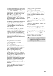
Regulatory Information
Declaration of Conformity
Trade Name:
SONY
Model No.:
PCV-RX462DS PCV-RX463DS PCV-RX465DS PCV-RX470DS PCV-RX480DS PCV-RX490TV
Responsible Party: Sony Electronics Inc.
Address:
680 Kinderkamack Rd Oradell, NJ 07649
Telephone:
201-930-6972
This phone number is for FCC-related matters only.
This device...
System Reference Manual - Page 7
...., Fort Myers, FL 33913. If the trouble is causing harm to the telephone network, the telephone company may request that you remove the equipment from the network until the problem is resolved.
Repair of this equipment should be made only by a Sony Service Center or Sony authorized agent. For the Sony Service Center nearest you, call 1-888-4SONYPC...
System Reference Manual - Page 9
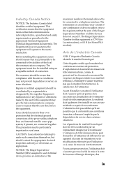
... telecommunications network protective...installed using an acceptable method of connection.
The customer should be aware that compliance with the above conditions may not prevent degradation of service... ground connections of the power utility, telephone lines and...devices does not exceed 5. The Ringer Equivalence Number for this equipment is 0.79 B (for Lucent modem), or 0.0 B (for HomePNA modem...
System Reference Manual - Page 12
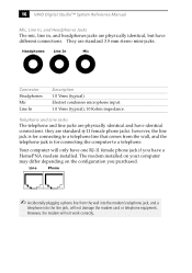
... and Headers 54 Front Panel Header 54 Floppy Disk Drive Header 55 Memory Module (RIMM) Slots 56 PCI Slots 57 AGP Slot 58 IDE Headers 59 Power Supply and Aux Power Headers 60 Keyboard and Mouse Ports 62 USB Ports and USB Header 63 Ethernet Port 65 Serial , Printer, and i.LINK Ports 65 Fan Headers 69 Game Port 70 Headphones, Line In, Mic Jacks 71 i.LINK...
System Reference Manual - Page 30
... the computer to a telephone.
Your computer will only have one RJ-11 female phone jack if you have a HomePNA modem installed. The modem installed on your computer may differ depending on the configuration you purchased.
Line
Phone
✍ Accidentally plugging a phone line from the wall into the modem's telephone jack, and a
telephone into the line jack, will not damage the modem card or...
System Reference Manual - Page 31
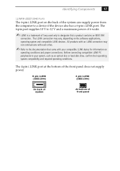
... your compatible i.LINK device for information on
operating conditions and proper connections. Before connecting compatible i.LINK PC peripherals to your system, such as an optical disc or hard disk drive, confirm their operating system compatibility and required operating conditions.
The 4-pin i.LINK port at the bottom of the front panel does not supply power.
6-pin i.LINK...
System Reference Manual - Page 41
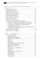
... Replacing Components
This chapter describes removing, installing, and replacing major components for upgrading, reconfiguring, and troubleshooting the components.
! Before opening the system unit, save and close all open files, exit all open
applications, turn off the power to all attached peripheral devices, shut down the computer, and unplug the power cord.
✍ Systems differ by model...
System Reference Manual - Page 43
Removing, Installing, and Replacing Components
29
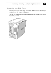
Replacing the Side Cover
1 From the rear of the unit, align the bottom of the cover so that it slips
into the lip on the bottom of the unit.
2 Push the top of the cover up against the top of the unit until the cover
snaps into position.
System Reference Manual - Page 44
30 VAIO Digital Studio™ System Reference Manual
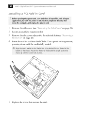
Installing a PCI Add-In Card
! Before opening the system unit, save and close all open files, exit all open
applications, turn off the power to all attached peripheral devices, shut down the computer, and unplug the power cord.
1 Remove the side cover (see "Removing the Side Cover" on page 28). 2 Locate an available...
System Reference Manual - Page 45
Removing, Installing, and Replacing Components
31
6 Attach any necessary cables to the card (see the instructions that came
with the add-in card).
7 Replace the side cover (see "Replacing the Side Cover" on page 29).
8 Turn on the computer and follow any instructions that came with the
add-in card.
System Reference Manual - Page 47
... exposed metal part on the metal chassis (preferably the metal part on the power supply) before handling an add-in card to discharge any static electricity in your body.
5 If you do not replace the card or install another add-in card, install a
slot cover over the vacant slot at the rear of the chassis (see...
System Reference Manual - Page 49
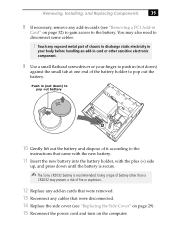
...battery and dispose of it according to the
instructions that came with the new battery.
11 ...Sony CR2032 battery is recommended. Using a type of battery other than a
CR2032 may present a risk of fire or explosion.
12 Replace any add-in cards that were removed. 13 Reconnect any cables that were disconnected. 14 Replace the side cover (see "Replacing the Side Cover" on page 29). 15 Reconnect the power...
System Reference Manual - Page 51
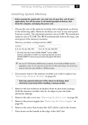
... models ship with at least 128 MB of RIMM™ memory. RIMM memory is expandable to 512 MB. Your model may ship with more than 128 MB of RIMM™ memory if you purchased it through the VAIO Direct Web site.
✍ Use only PC-800 Rambus RIMM memory modules. Direct Rambus RIMMS must be
upgraded in pairs. Do not leave...
System Reference Manual - Page 53
Removing, Installing, and Replacing Components
39
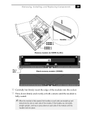
RIMMB 1 RIMMB 2
RIMMA 1 RIMMA 2
Handles
Memory module (in RIMM A1/B1)
WARNING HOT
A1
Pin 1 side
A4
A4
A9
6
7
2
Blank memory module (CRIMM)
A1
A1
A4
A4
A9
6
7
2
10 Carefully but firmly insert the edge of the module into the socket.
11 Press down firmly and ...
System Reference Manual - Page 55
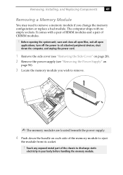
... files, exit all open
applications, turn off the power to all attached peripheral devices, shut down the computer, and unplug the power cord.
1 Remove the side cover (see "Removing the Side Cover" on page 28). 2 Remove the power supply (see "Removing the Power Supply" on
page 50).
3 Locate the memory module you wish to remove.
✍ The...
System Reference Manual - Page 57
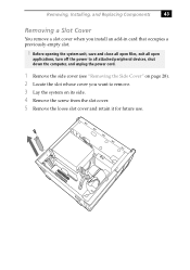
... Cover
You remove a slot cover when you install an add-in card that occupies a previously-empty slot.
! Before opening the system unit, save and close all open files, exit all open
applications, turn off the power to all attached peripheral devices, shut down the computer, and unplug the power cord.
1 Remove the side cover (see "Removing...
System Reference Manual - Page 63
Removing, Installing, and Replacing Components
49
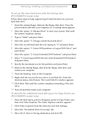
To set up the new hard drive with the startup disk (PCV-RX490TV model only)
Follow these steps to help support Giga Pocket functions in your new hard disk drive.
1 Insert the startup floppy disk into the floppy disk drive. Press the
power button and turn your computer on. A startup menu appears.
2 Select the option "4. Minimal Boot" to...
System Reference Manual - Page 127
...
113
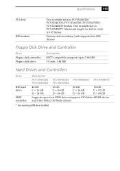
PCI slots IDE headers
Two available slots in PCV-RX462DS/ PCV-RX463DS/PCV-RX465DS/PCV-RX470DS/ PCV-RX480DS models. One available slot in PCV-RX490TV. Maximum length for add-in cards is 9.05 inches
Primary and secondary (each supports two IDE drives)
Floppy Disk Drive and Controller
Drive Floppy disk controller Floppy disk drive
Description 82077-compatible (supports up to 2.88 MB...