Dell IP4700 driver and firmware


Related Dell IP4700 Manual Pages
Download the free PDF manual for Dell IP4700 and other Dell manuals at ManualOwl.com
Service Guide - Page 2
..., EDM, SDMS, SRDF, Timefinder, PowerPath, InfoMover, FarPoint, EMC Enterprise Storage Network, EMC Enterprise Storage Specialist, EMC Storage Logic, Universal Data Tone, E-Infostructure, Celerra, Access Logix, MirrorView, and SnapView are trademarks of EMC Corporation.
. All other trademarks mentioned herein are the property of their respective owners
ii
IP4700 Installation and Service Guide
Service Guide - Page 6
...23
Chapter 3
Servicing and Upgrading an IP4700
Monitoring IP4700 Status 3-2 Handling CRUs 3-5
Power Issues and CRUs 3-5 Avoiding Electrostatic Discharge (ESD) Damage 3-6 Replacing or Adding a Disk Module 3-8 Replacing the Storage Processor Fan Pack 3-13 Replacing a Storage Processor 3-15 Installing a Storage Processor 3-16 Replacing a Link Control Card 3-17 Replacing the Drive Fan Pack...
Service Guide - Page 9
... that accompany the mounting kit.
If you will install and service the IP4700, you should read this manual. After reading it, you will be able to
• install an IP4700
• upgrade an IP4700 by adding disk modules and disk-array enclosures (DAEs)
• replace failed CRUs
• install, service, and use the DC Standby Power Supply (DC SPS)
IP4700 Installation and Service Guide
ix
Service Guide - Page 10
... is located in this manual: Chapter 1 introduces the IP4700's components. Chapter 2 explains requirements and describes how to install the IP4700 and cable it to the LAN and to Disk Array Enclosures (DAEs). Chapter 3 describes how to replace CRUs such as disk modules. Chapter 4 introduces the Standby Power Supply (SPS) and explains how to install and connect cables to them. In addition...
Service Guide - Page 11
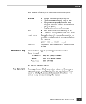
...you would type, displayed text, or ...Obtain technical support by calling your local sales office.
For service, call...Service.
Your suggestions will help us continue to improve the accuracy, organization, and overall quality of the user publications. Please e-mail us at [email protected] to let us know your opinion or any errors concerning this manual.
IP4700 Installation and Service Guide...
Service Guide - Page 40
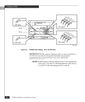
...: Use only category 5 Ethernet cable to connect an IP4700 to a 10/100 local area network. For specific information about subnet requirements refer to the IP4700 Quick Start Guide (069701170).
NOTE IP4700 system software releases prior to 2.0 number the LAN ports 1 (for the 10/100 management LAN), then 2, 3, 4, and 5 for the remaining ports on each SP.
2-4
IP4700 Installation and Service Guide
Service Guide - Page 41
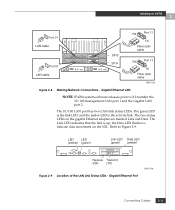
...Port 01 LAN cable
Port 01 LAN cable
SP B SP A
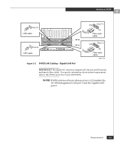
Figure 2-3 IP4700 LAN Cabling - Gigabit LAN Port
RX
Port 11
TX
Fiber optic cable
RX
Port 11
TX
Fiber optic cable
EMC1729
IMPORTANT: The duplex SC connector supports 62.5-micron and 50-micron multimode fibre cables. For specific information about subnet requirements refer to the IP4700 Quick Start Guide (069701170).
NOTE IP4700 system software...
Service Guide - Page 46
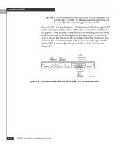
... the right. The location of the LEDs on the remaining subnet ports (2-5) are just the opposite; the amber LED is on the right, the green LED is on the left. Refer to Figure 2-7.
LED (green)
LED (amber)
LED (green)
EMC1472
Figure 2-7 Location of the LAN Link Status LEDs - 10/100 Ethernet Ports
2-10
IP4700 Installation and Service Guide
Service Guide - Page 47
Installing an IP4700
2
Port 01 LAN cable
Port 01 LAN cable
SP B SP A
RX
Port 11
TX
Fiber optic cable
RX
Port 11
TX
Fiber optic cable
EMC1729
Figure 2-8 Making Network Connections - Gigabit Ethernet LAN
NOTE IP4700 system software releases prior to 2.0 number the 10/100 management LAN port 1 and the Gigabit LAN port 2.
The 10/100 LAN port has two LAN link status LEDs. The green LED is the ...
Service Guide - Page 49
... storage processor to each connector on the tape drive, or use a Y cable.
After the next system boot, you can verify that the IP4700 has scanned the SCSI buses and found your tape device(s) by clicking Tape Drives in the IP4700 system display. Refer to your NDMP backup software documentation for further configuration instructions.
Library changer
Differential tape drive
To ac power
To ac power...
Service Guide - Page 62
... in Figure 3-5, to examine the storage processor fan pack fault LED.
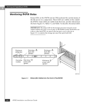
Enclosure addresses
0
02 4 13 5 #
1
6 8 10 7 9 11 #
2
Disk drive fault LED (amber)
3
4
5
Disk drive Disk drive number active LED
(green)
Enclosure fault LED (amber)
6
7
8
9
Enclosure power LED (green)
Figure 3-1 Status LEDs Visible from the Front of the IP4700
EMC1443
3-2
IP4700 Installation and Service Guide
Service Guide - Page 64
Servicing and Upgrading an IP4700
3
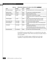
Table 3-2 Status LEDs Visible from the Back of the IP4700 (continued)
Light
Quantity
Color
Meaning
Link control card fault
1 per link control Amber card
On when either the LCC or a FC-AL connection is faulty.
LAN link (10/100)
1 per port
Green
On when there is a valid Ethernet connection.
LAN activity (10/100)
1 per port
Amber
Blinks during ...
Service Guide - Page 65
... compartments should contain either a CRU or, in the case of a disk drive, a filler panel, to ensure EMI compliance and proper air flow over the CRUs.
While the IP4700 is powered up, you can service or replace any CRU. However, removing an active link control card or storage processor will affect performance and may temporarily impair operating system access to...
Service Guide - Page 66
Servicing and Upgrading an IP4700
3
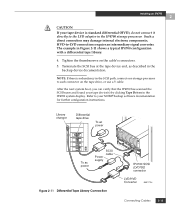
3. Shut off the power to each SPS
4. Remove the drive fan pack (see Replacing the Drive Fan Pack on page 3-20.), and set the power switch on each power supply to the off (0) position.
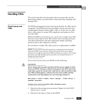
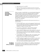
Avoiding Electrostatic Discharge (ESD) Damage
When you replace or install... and understand the following instructions before you access any ...IP4700 Installation and Service Guide
Service Guide - Page 67
Servicing and Upgrading an IP4700
3
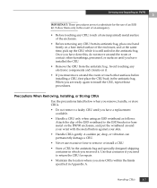
IMPORTANT: These procedures are not a substitute for the use of an ESD kit. Follow them only... CRUs gently. A sudden jar, drop, or vibration can permanently damage a CRU.
• Never use excessive force to remove or install a CRU.
• Store a CRU in the antistatic bag and specially designed shipping container in which you received it. Use that container...
Service Guide - Page 68
Servicing and Upgrading an IP4700
3
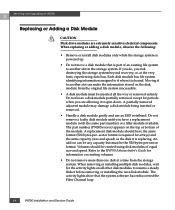
Replacing or Adding a Disk Module
!
CAUTION
Disk drive modules are extremely sensitive electrical components.
When replacing or adding a disk module, observe the following:
• Remove or install disk modules only while the storage system is powered up.
• Do not move a disk module that is part of an existing file system to another slot in the ...
Service Guide - Page 70
Servicing and Upgrading an IP4700
3
EMC1446
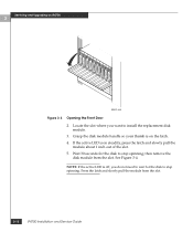
Figure 3-3 Opening the Front Door
2. Locate the slot where you want to install the replacement disk module.
3. Grasp the disk module handle so your thumb is on the latch. 4. If the active LED is on steadily, press the latch and slowly pull the
module about 1 ...
Service Guide - Page 71
Servicing and Upgrading an IP4700
3
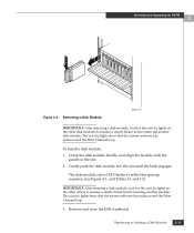
Figure 3-4 Removing a Disk Module
EMC1447
IMPORTANT: After removing a disk module, wait for the activity lights on the other disk modules to resume a steady flicker before removing another disk module. The activity lights show that the system software has rediscovered the Fibre Channel loop.
To install a disk module: 1. Grasp the disk module handle, and align...
Service Guide - Page 72
Servicing and Upgrading an IP4700
3
4. Close and lock the front door.
IMPORTANT: The door must be closed for EMI compliance when the IP4700 is powered up.
3-12
IP4700 Installation and Service Guide
Service Guide - Page 78
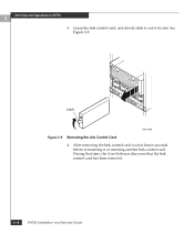
... the link control card, and slowly slide it out of its slot. See Figure 3-9.
Latch
EMC1460
Figure 3-9 Removing the Link Control Card 4. After removing the link control card, wait at least 6 seconds before re-inserting it or inserting another link control card. During that time, the Core Software discovers that the link control card has been removed.
3-18
IP4700 Installation and Service Guide