Dell Latitude C500 driver and firmware
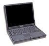
Related Dell Latitude C500 Manual Pages
Download the free PDF manual for Dell Latitude C500 and other Dell manuals at ManualOwl.com
Service Manual - Page 4
...reserved. Reproduction in any manner whatsoever without the written permission of Dell Computer Corporation is strictly forbidden. Trademarks used in this text: Dell, the DELL logo, and DellWare are trademarks of Dell Computer Corporation; Intel is a registered trademark of Intel Corporation; Microsoft and Windows are registered trademarks of Microsoft Corporation. Other trademarks and trade names...
Service Manual - Page 10
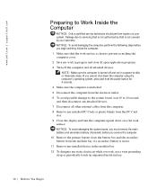
... the power button for 4 seconds. 4 Make sure the computer is undocked. 5 Disconnect the computer from the electrical outlet. 6 To avoid possible damage to the system board, wait 10 to 20 seconds and then disconnect any attached devices. 7 Disconnect all other external cables from the computer. 8 Remove any installed PC Cards or plastic blanks from the PC Card slot. 9 Close the display...
Service Manual - Page 11
..., not by its pins.
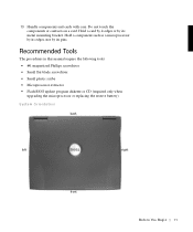
Recommended Tools
The procedures in this manual require the following tools: • #1 magnetized Phillips screwdriver • Small flat-blade screwdriver • Small plastic scribe • Microprocessor extractor • Flash BIOS update program diskette or CD (required only when
upgrading the microprocessor or replacing the reserve battery)
System Orientation
back
left...
Service Manual - Page 17
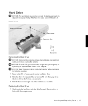
... by its edges (do not squeeze the top of the hard drive case), and avoid dropping it.
Hard Drive
bottom of computer
M3 x 5-mm screw hard drive door
Removing the Hard Drive
NOTICE: Disconnect the computer and any attached devices from electrical outlets, and remove any installed batteries. NOTICE: To avoid ESD, ground yourself by using a wrist grounding...
Service Manual - Page 18
www.dell.com | support.dell.com
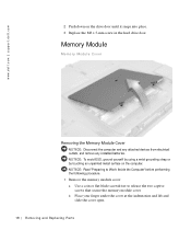
2 Push down on the drive door until it snaps into place. 3 Replace the M3 x 5-mm screw in the hard drive door.
Memory Module
Memory Module Cover
Removing the Memory Module Cover
NOTICE: Disconnect the computer and any attached devices from electrical outlets, and remove any installed batteries. NOTICE: To avoid ESD, ground yourself by using a wrist...
Service Manual - Page 19
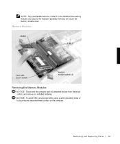
... cover secures the keyboard assembly and does not secure the memory module cover.
Memory Modules
JDIM 1
JDIM 2
inner tabs (2 per socket)
memory module sockets (2)
Removing the Memory Modules
NOTICE: Disconnect the computer and any attached devices from electrical outlets, and remove any installed batteries.
NOTICE: To avoid ESD, ground yourself by using a wrist grounding strap or by...
Service Manual - Page 20
... the bottom case assembly. Rotate the memory module cover down and tighten the two captive screws.
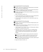
Mini-PCI Card Assembly
You must remove the optional mini-PCI card assembly before the system board assembly can be removed. A mini-PCI card assembly may consist of a modem, a NIC, a modem and NIC combination, or a wireless NIC. A modem, NIC, or modem and NIC combination must be connected...
Service Manual - Page 22
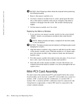
... the metal securing tabs.
NOTE: If you are installing a wireless NIC, fold and tuck the unused interface cables into the slot so they do not interfere with the cover. NOTE: A modem-only mini-PCI card has one connector; place the unused NIC connector under the mini-PCI card. 4 Replace the memory module cover.
22 Removi ng and Replacing Parts
Service Manual - Page 23
...: Disconnect the computer and any attached devices from electrical outlets, and remove any installed batteries. NOTICE: To avoid ESD, ground yourself by using a wrist grounding strap or by touching an unpainted metal surface on the computer. NOTICE: Read "Preparing to Work Inside the Computer" before performing the following procedure. 1 Remove the hard drive. 2 Turn the computer over...
Service Manual - Page 26
...dell.com | support.dell.com
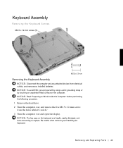
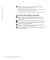
NOTICE: Position the keyboard flex cable so it is not pinched when you replace the keyboard in the bottom case assembly. 4 Check that the keyboard is correctly installed...Always remove and replace the display panel as a complete assembly. NOTICE: Disconnect the computer and any attached devices from electrical outlets, and remove any installed batteries. NOTICE: To avoid...
Service Manual - Page 30
www.dell.com | support.dell.com
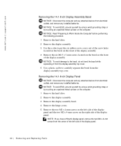
Removing the 14.1-Inch Display Assembly Bezel
NOTICE: Disconnect the computer and any attached devices from electrical outlets, and remove any installed batteries. NOTICE: To avoid ESD, ground yourself by using a wrist grounding strap or by touching an unpainted metal surface on the computer. NOTICE: Read "Preparing to Work Inside the Computer" before performing...
Service Manual - Page 32
www.dell.com | support.dell.com
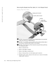
Removing the Display-Feed Flex Cable (14.1-Inch Display Panel)
Display-Feed Flex Cable
display panel connector top flex cable connector pull tab bottom flex cable connector
inverter connector
NOTICE: Disconnect the computer and any attached devices from electrical outlets, and remove any installed batteries. NOTICE: To avoid ESD, ground yourself by using a wrist ...
Service Manual - Page 34
www.dell.com | support.dell.com
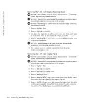
Removing the 12.1-Inch Display Assembly Bezel
NOTICE: Disconnect the computer and any attached devices from electrical outlets, and remove any installed batteries. NOTICE: To avoid ESD, ground yourself by using a wrist grounding strap or by touching an unpainted metal surface on the computer. NOTICE: Read "Preparing to Work Inside the Computer" before performing...
Service Manual - Page 36
www.dell.com | support.dell.com
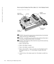
Removing the Display-Feed Flex Cable (12.1-Inch Display Panel)
Display-Feed Flex Cable
bottom flex cable connector
pull tab
top flex cable connector
inverter connector
display panel connector
NOTICE: Disconnect the computer and any attached devices from electrical outlets, and remove any installed batteries.
NOTICE: To avoid ESD, ground yourself by using a ...
Service Manual - Page 37
... the attached pull tab.
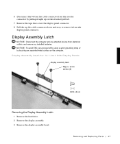
7 Remove the tape that covers the display panel connector. 8 Pull the top flex cable connector down and away to remove it from the
display panel connector.
Display Assembly Latch
NOTICE: Disconnect the computer and any attached devices from electrical outlets, and remove any installed batteries. NOTICE: To avoid ESD, ground yourself by using...
Service Manual - Page 41
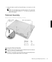
...display assembly and snap the hinge covers in place over the hinges.
NOTE: The right plastic hinge cover label includes an "R," and the left plastic hinge cover label includes an "L." The hinge cover labels face the back of the computer... the Palmrest Assembly
NOTICE: Disconnect the computer and any attached devices from electrical outlets, and remove any installed batteries. NOTICE: To avoid ESD, ...
Service Manual - Page 44
www.dell.com | support.dell.com
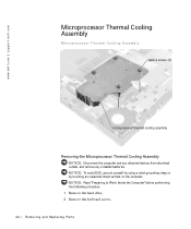
Microprocessor Thermal Cooling Assembly
Microprocessor Thermal Cooling Assembly
captive screws (4)
microprocessor thermal cooling assembly
Removing the Microprocessor Thermal Cooling Assembly
NOTICE: Disconnect the computer and any attached devices from electrical outlets, and remove any installed batteries. NOTICE: To avoid ESD, ground yourself by using a wrist ...
Service Manual - Page 49
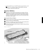
...: For instructions to update or flash the BIOS, see the Dell Portable Computer BIOS Update Guide.
Reserve Battery
NOTICE: The reserve battery provides power to the computer's RTC and NVRAM when the computer is turned off. Removing the battery causes the computer to lose the date and time information as well as all user-specified parameters in the BIOS. If possible, make a copy of this...
System Information Guide - Page 4
...includes descriptions of
computer features, instructions on installing and configuring drivers and utilities, information on the System Setup program, and instructions for attaching devices to the connectors on your computer's back panel. The User's Guide is located on your hard-disk drive. You may also have one or more of the following documents:
• Documentation updates, which are sometimes...
System Information Guide - Page 14
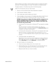
... battery from the battery bay:
a. Close the computer display and turn the computer over.
b. Slide the battery bay to the side (see Figure 1-6). Hold the latch with one hand while pulling the battery out of the bay with the other hand.
c. Release the latch after you remove the battery.
support.dell.com
Dell Latitude System Information 1-11