Dell OptiPlex GXpro driver and firmware

Related Dell OptiPlex GXpro Manual Pages
Download the free PDF manual for Dell OptiPlex GXpro and other Dell manuals at ManualOwl.com
Service Manual - Page 2

... in any manner whatsoever without the written permission of Dell Computer Corporation is strictly forbidden.
Trademarks used in this text: Dell, the DELL logo, and OptiPlex are registered trademarks of Dell Computer Corporation; Intel and Pentium are registered trademarks of Intel Corporation; Microsoft, MS-DOS, Windows, and Windows NT are registered trademarks of Microsoft Corporation; Novell and...
Service Manual - Page 9

Chapter 1
System Overview
This service manual covers the Dell® OptiPlex® GXpro high-speed, upgrad-
able desktop systems, which use the Intel® Pentium® Pro family of microprocessors. These Dell systems incorporate the high-performance PCI local bus as well as the ISA expansion bus. These buses are built into the system board, which also integrates a 3.3-V Pentium Pro ...
Service Manual - Page 13
...operating systems. The microprocessor chips on both the system board and the processor card are replaceable.
Advanced Expansion Subsystem
The computer system offers advanced expansion subsystems that can support a mixture of traditional ISA expansion cards (called legacy cards), Plug and Play ISA expansion cards, and PCI expansion cards. The ISA Configuration Utility (ICU) included with the system...
Service Manual - Page 14
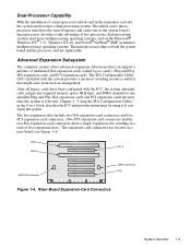
..., "Hard-Disk Drive Options." For detailed information about the data storage subsystem, see Chapter 9, "Installing Drives," in the User's Guide.
Audio Controller
The system board has a built-in 16-bit Creative Labs ViBRA 16 audio controller chip and connectors on the back panel for connecting the system unit to external audio devices (speakers, microphone). The controller supports all the...
Service Manual - Page 15
... 10/100-Mbps NIC. Chapter 5, "Using the Network Interface Controller," in the User's Guide provides instructions for connecting the system to, and configuring it for use on, an Ethernet network.
USB
USB capability simplifies connection of peripheral devices such as mice, printers, and computer speakers. The USB connectors on your computer's back panel provide a single connection point for multiple...
Service Manual - Page 20
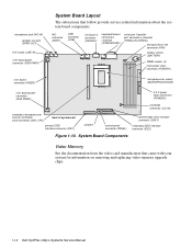
... (IDE1)
jumpers
control panel connector (PANEL)
diskette/tape drive interface connector (DSKT)
secondary EIDE interface connector (IDE2)
Figure 1-10. System Board Components
Video Memory
See the documentation from the video card manufacturer that came with your system for information on removing and replacing video-memory upgrade chips.
1-12 Dell OptiPlex GXpro Systems Service Manual
Service Manual - Page 21
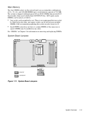
.... Dell recommends populating the sockets in order from A to D.
• Each DIMM socket does not have to contain DIMMs of the same size or
speed. DIMMs may be installed in any order.
See "DIMMs" in Chapter 4 for information on removing and replacing DIMMs.
System Board Jumpers
jumpered unjumpered
Figure 1-11. System Board Jumpers
System...
Service Manual - Page 22
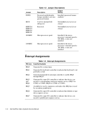
... for COM2 or COM4; IRQ4 for COM1 or COM3).
IRQ5
Available for use by expansion card unless this IRQ line is used by secondary parallel port.
IRQ6
Generated by super I/O controller to indicate that diskette or tape drive requires service.
IRQ7
Generated by super I/O controller to indicate that device connected to parallel port requires service.
1-14 Dell OptiPlex GXpro Systems Service Manual
Service Manual - Page 23
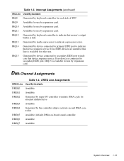
... Available for use by expansion card.
IRQ11 Available for use by expansion card.
IRQ12 Generated by keyboard controller to indicate that mouse's output buffer is full.
IRQ13 Generated by math coprocessor to indicate coprocessor error.
IRQ14
Generated by device connected to primary EIDE port to indicate that device requires service. If no EIDE devices are installed, this line is available...
Service Manual - Page 27
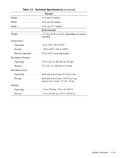
....9 cm (16.5 inches) Depth 44.5 cm (17.5 inches)
Environmental
Weight 12.7 kg (28 lb) or more, depending on options installed
Temperature: Operating 10° to 35°C (50° to 95°F) Storage 40° to 65°C (-40° to 149°F) Relative humidity 8% to 80% (noncondensing)
Maximum vibration: Operating 0.25...
Service Manual - Page 33
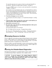
... card-mounting bracket's retaining screw. 4. Verify that all jumpers are set correctly. For information about these jumpers, see "System Board Jumpers" in Chapter 1. 5. Check all cable ...computer system.
CAUTION: To prevent damage to the original diagnostics diskette, always use a backup copy of the diagnostics diskette when servicing a user's system. Dell recommends that users make several copies...
Service Manual - Page 37
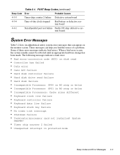
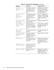
...made. The following messages indicate a fatal error:
• Bad error-correction code (ECC) on disk read • Controller has failed • Data error • Gate A20 failure • Hard disk controller failure • Hard disk drive read failure • Hard disk failure • Incompatible Processor: CPU0 is B0 step or below • Incompatible Processor: CPU1 is B0 step or below •...
Service Manual - Page 39
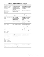
...Operating system corrupted or not installed properly.
Hard disk controller failure
Hard disk drive read failure
Hard disk failure
Hard-disk drive failed to initialize.
Incorrect configuration settings in System Setup program, improperly connected hard-disk drive cable, faulty hard-disk controller subsystem (defective system board), or loose power cable.
Incompatible Processor: CPU0 is B0 step...
Service Manual - Page 41
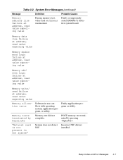
... at address, read value expecting value
Memory allocation error
Memory tests terminated by keystroke
"Network card is not present in the system"
Software in use conflicts with operating system, application program, or utility.
Memory test did not complete.
System does not detect NIC.
Faulty application program or utility.
POST memory test terminated by pressing . Incorrect NIC drivers installed...
Service Manual - Page 42
....
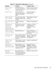
Requested sector not found
System could not find particular sector on disk, or requested sector defective.
Faulty diskette, diskette/ tape drive subsystem, or hard-disk drive subsystem (defective system board).
Reset failed
Disk reset operation failed.
Improperly connected diskette/tape drive, harddisk drive interface cable, or power cable.
3-8 Dell OptiPlex GXpro Systems Service Manual
Service Manual - Page 43
... hard-disk drive.
or hard-disk drive.
Seek error
MS-DOS unable to locate specific track on diskette or hard-disk drive.
Defective diskette or hard-disk drive.
Seek operation failed
System could not find Faulty diskette or hardparticular address mark disk drive. on disk.
Shutdown fail- System board chip
ure
faulty.
Defective system board.
Terminator/ processor card not installed! System...
Service Manual - Page 48
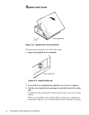
...Removal
To remove the system unit cover, follow these steps: 1. Remove the padlock if one is installed.
back of system unit
Figure 4-3. Padlock Removal 2. Press in the two securing buttons until the cover...reinstall the cover, fold all cables out of the way so that they do not interfere with the cover or with the proper airflow inside the system unit.
4-4 Dell OptiPlex GXpro Systems Service Manual
Service Manual - Page 53
...
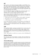
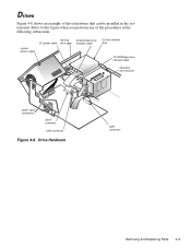
Figure 4-8 shows an example of drive hardware that can be installed in the system unit. Refer to this figure when you perform any of the procedures in the following subsections.
system power supply
two-bay DC power cable drive cage
diskette/tape drive interface cable
3.5-inch diskette drive
CD-ROM/tape drive interface cable
hard-disk drive bracket
power input connectors
DSKT connector
IDE2...
Service Manual - Page 61
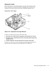
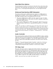
... fit into connectors on a riser board. Dell recommends that you remove the expansion-card cage first before removing or installing expansion cards.
Expansion-Card Cage
lever expansioncard cage
notch
chassis
Figure 4-16. Expansion-Card Cage Removal To remove an expansion-card cage, follow these steps: 1. Disconnect any cables from the expansion cards and the riser board. 2. Rotate the lever toward...
Service Manual - Page 67
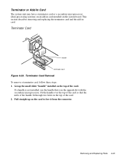
...-in card installed on the system board. This section describes removing and replacing the terminator card and the add-in card.
Terminator Card
handle
terminator card
Figure 4-23. Terminator Card Removal To remove a terminator card, follow these steps: 1. Grasp the small white "handle" installed on the top of the card.
If a handle is not installed, use the handle that is in the upgrade...