Dell PowerEdge 1750 driver and firmware

Related Dell PowerEdge 1750 Manual Pages
Download the free PDF manual for Dell PowerEdge 1750 and other Dell manuals at ManualOwl.com
Microprocessor
Upgrade Installation Guide - Page 3
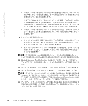
... replace a microprocessor, check the latest system BIOS information on the Dell Support website at support.dell.com, and upgrade the BIOS if necessary.
Each microprocessor and its associated cache memory are contained in a pin-grid array (PGA) package that is installed in a ZIF socket on the system board. The following subsection describes how to install or replace the microprocessor in either...
Microprocessor
Upgrade Installation Guide - Page 4
www.dell.com | support.dell.com
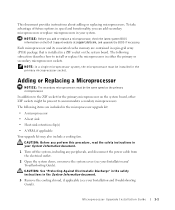
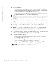
4 If you are upgrading an existing microprocessor, remove the microprocessor heat sink.
NOTE: If a cooling fan is mounted on the heat sink, you can ... microprocessor.
7 Unpack the new microprocessor.
If any of the pins on the microprocessor appear bent, see "Getting Help" in your Installation and Troubleshooting Guide.
1-2
Microprocessor Upgrade Installation Guide
Microprocessor
Upgrade Installation Guide - Page 5
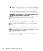
...Align pin 1 on the microprocessor with pin 1 on the microprocessor socket.
c With pin 1 of the microprocessor and socket aligned, set the microprocessor lightly in the socket and ensure that all pins are matched with the correct holes in the socket.
Because the system...lever back down until it snaps into place, locking the microprocessor in the socket.
Microprocessor Upgrade Installation Guide
1-3
Microprocessor
Upgrade Installation Guide - Page 6
....dell.com | support.dell.com
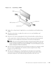
9 Install ...mark on the system board, if applicable.
10 Orient the heat-sink retention clip as shown in your Installation and Troubleshooting Guide.
11 Hook the ... upgrade kit, replace the primary VRM already installed in the system with one of the VRMs from the upgrade kit.
NOTE: The system does not support mismatched VRMs.
1-4
Microprocessor Upgrade Installation Guide
Microprocessor
Upgrade Installation Guide - Page 7
... stored in the system's nonvolatile random-access memory (NVRAM). To clear this message log, see your systems management software documentation.
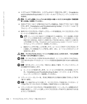
18 Enter the System Setup program and ensure that the microprocessor categories match the new system configuration. For instructions about using the System Setup program, see your User's Guide.
19 Run the system diagnostics to verify...
Microprocessor
Upgrade Installation Guide - Page 34
www.dell.com | support.dell.com
2 Installation and Troubleshooting Guide
3 Installation and Troubleshooting Guide
4
Installation and Troubleshooting Guide
a
b Installation and Troubleshooting Guide
5 5-1
6
5-2
Microprocessor
Upgrade Installation Guide - Page 35
7
Installation and Troubleshooting Guide
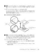
図 5-1
ピン 1
ZIF
8 5-1
a
b 1 1
5-3
Microprocessor
Upgrade Installation Guide - Page 36
www.dell.com | support.dell.com
c 1
ZIF
d
9
10 『Installation and Troubleshooting Guide
11
12 ZIF
Installation and Troubleshooting Guide
13
5-4
Microprocessor
Upgrade Installation Guide - Page 37
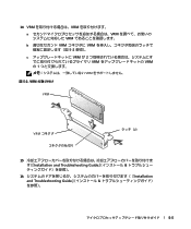
14 VRM VRM a VRM VRM b VRM VRM 5-2 c VRM が 2 VRM VRM の 1 VRM
図 5-2. VRM
VRM
VRM
ラッチ(2)
15 Installation and Troubleshooting Guide
16 Installation and Troubleshooting Guide
5-5
Microprocessor
Upgrade Installation Guide - Page 38
www.dell.com | support.dell.com
17
NVRAM RAM
18
19 Installation and Troubleshooting Guide
5-6
Information Update (.pdf) - Page 5
... software solutions designed to provide remote management capabilities for PowerEdge™ systems. Collectively, these solutions are known as remote access controllers (RACs). RACs allow you to remotely manage and monitor your system even when the system is down.
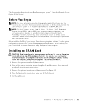
Before installing the ERA/O card, record the system configuration settings. View the system configuration screens in the System Setup...
Information Update (.pdf) - Page 6
www.dell.com | support.dell.com
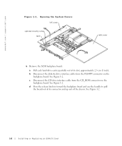
Figure 1-1. Opening the System Covers left cover
optional security screw latch
right cover
6 Remove the SCSI backplane board:
a Pull each hard-drive carrier partially out of its slot, approximately 2.5 cm (1 inch).
b Disconnect the diskette-drive interface cable from the FLOPPY connector on the backplane board. See Figure 1-2.
c Disconnect the CD drive interface ...
Information Update (.pdf) - Page 7
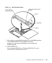
Figure 1-2. SCSI Backplane Board
CD drive interface connector (CD_ROM)
diskette drive interface connector (FLOPPY)
handle
release latch tabs (2)
7 If the system has an optional ROMB card installed, remove the ROMB backup battery (not the ROMB card itself) to expose the ERA/O card connector.
See Figure 1-3; see also "Removing a ROMB Card" in your Installation and Troubleshooting Guide.
8 Unpack ...
Information Update (.pdf) - Page 8
www.dell.com | support.dell.com
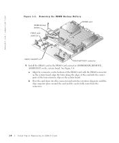
Figure 1-3. Removing the ROMB Backup Battery
ROMB backup battery
ROMB card
ERA/O card connector
battery standoffs (2)
RAID BATTERY connector
9 Install the ERA/O card in the ERA/O card connector (EMBEDDED_REMOTE_ ASSISTANT) on the system board. See Figure 1-4.
a Align the connector on the bottom of the ERA/O card with the ERA/O connector on the system board; ...
Information Update (.pdf) - Page 9
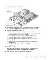
... latch out into the securing slot in the chassis. d Connect the CD drive interface cable to the CD_ROM connector on the
backplane board. e Connect the diskette-drive interface cable to the FLOPPY connector on the
backplane board. f Press all installed hard drives firmly back into the SCSI connectors on the
backplane.
12 Close the system covers.
When closing the...
Information Update (.pdf) - Page 10
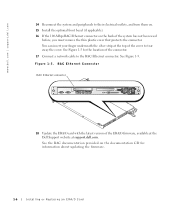
...17 Connect a network cable to the RAC Ethernet connector. See Figure 1-5.
Figure 1-5. RAC Ethernet Connector
RAC Ethernet connector
18 Update the ERA/O card with the latest version of the ERA/O firmware, available at the Dell Support website at support.dell.com.
See the RAC documentation provided on the documentation CD for information about updating the firmware.
1-6
Installing or Replacing an...
Information Update (.pdf) - Page 11
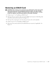
... two retention clips nearest the ERA/O card connector while lifting that end of the card from the connector. See Figure 1-4.
3 Push open the remaining two retention clips and remove the card completely.
4 Perform steps 10-15 in "Installing an ERA/O Card."
5 Disconnect the network cable from the RAC Ethernet connector (if applicable). See Figure 1-5.
Installing or Replacing an ERA...
Installation and
Troubleshooting Guide (.htm) - Page 22
...dell.com | support.dell.com
Replacing the Rack Doors
Refer to the procedures for replacing doors in the documentation provided with your rack cabinet.
CAUTION: Because of the size and weight of the rack cabinet doors, never attempt to remove or install them by yourself.
This completes the rack installation... enable the system to be pulled out for servicing.
You must properly secure the two-post, ...
Installation and
Troubleshooting Guide (.htm) - Page 29
...an 11/32-inch wrench or nut driver, remove two 12-24 x 0.5-inch ...step 2 (see Figure 1-17).
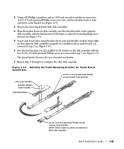
6 Join the front brackets you just installed to the bracket on the slide assembly with the two 12-24 x 0.5-...assembly.
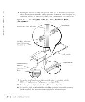
Figure 1-17. Rotating the Front Mounting Bracket for Flush-Mount Installation
12-24 x 0.5-inch pan-head Phillips screws (install 2 per bracket)
nuts (2 per bracket) shoulder washers (2 per ...
Installation and
Troubleshooting Guide (.htm) - Page 30
....dell.com | support.dell.com
8 Holding the left slide assembly into position in the rack at the location you marked, adjust the extended rear bracket tightly against the back of the vertical two-post rack and secure it to the rail with two 12-24 x 0.5-inch Phillips screws (see Figure 1-18).
Figure 1-18. Installing...