Dell PowerEdge 4400 driver and firmware

Related Dell PowerEdge 4400 Manual Pages
Download the free PDF manual for Dell PowerEdge 4400 and other Dell manuals at ManualOwl.com
Microprocessor
Upgrade Installation Guide - Page 3
...) FILE LOCATION: S:\SYSTEMS\SlimFast\ts\ProcUpgrade\028WD\028WDet0toc.fm
&RQWHQWV
)LJXUHV
Precautionary Measures 1-1 Before You Begin 1-2
Recording the System Configuration 1-2 Updating the ESM Firmware 1-3 Updating the BIOS 1-3 Saving RCU Configuration Settings 1-3 Installing an Upgrade Microprocessor in PowerEdge 2400 Systems 1-4 Removing the Cooling Shroud, SEC Cartridge, and Heat Sink...
Microprocessor
Upgrade Installation Guide - Page 5
...\ts\ProcUpgrade\028WD\028wdeb0.fm
'HOOŒ 3RZHU(GJH DQG 6\VWHPV ³ 0LFURSURFHV VRU 8SJUDGH ,QVWDOODWLRQ *XLGH
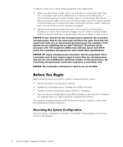
This document provides information on upgrading and installing microprocessors in Dell PowerEdge 2400, 2450, and 4400 systems.
3UHFDXWLRQDU\ 0HDVXUHV
Before you perform any of the procedures in this document, take a few moments to read the following warning for...
Microprocessor
Upgrade Installation Guide - Page 6
... them evenly aligned to avoid bending any connector pins. Also, before you connect a cable, make sure both connectors are correctly oriented and aligned.
‡ Handle components and cards with care. Don't touch the components or
contacts on a card. Hold a card by its edges or by its metal mounting bracket. Hold a component such as a microprocessor...
Microprocessor
Upgrade Installation Guide - Page 7
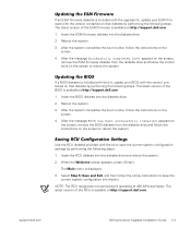
...kit, update your BIOS with the version contained on that diskette by performing the following steps. The latest version of the BIOS is available at http://support.dell.com.
1. Insert the BIOS diskette into the diskette drive.
2. Reboot the system.
3. After the system completes the boot routine, follow the instructions on the screen.
4. After the message BIOS has been successfully installed appears...
Microprocessor
Upgrade Installation Guide - Page 8
...\SlimFast\ts\ProcUpgrade\028WD\028wdeb0.fm
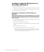
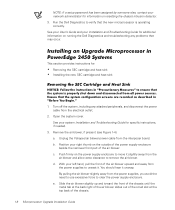
,QVWDOOLQJ DQ 8SJUDGH 0LFURSURFHVVRU LQ 3RZHU(GJH 6\VWHPV
This section provides instructions for:
‡ Removing the cooling shroud, single-edge contact (SEC) cartridge, and heat sink ‡ Installing the new SEC cartridge and heat sink and replacing the cooling shroud ‡ Reassembling and checking the system...
Microprocessor
Upgrade Installation Guide - Page 9
... EHIRUH \RX WRXFK WKHP
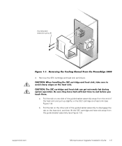
a. Pull the tab on one side of the guide-bracket assembly away from the end of the heat sink and pull up slightly...guide-bracket assembly to disengage the tab on the heat sink, and then lift the SEC cartridge and heat sink away from the guide-bracket assembly (see Figure 1-2).
support.dell.com
DELL CONFIDENTIAL - Preliminary 9/11/00
Microprocessor Upgrade Installation Guide...
Microprocessor
Upgrade Installation Guide - Page 10
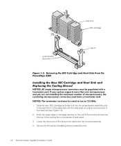
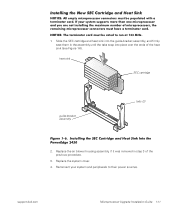
...7KH WHUPLQDWRU FDUG PXVW EH UDWHG WR UXQ DW 0+] 1. Slide the new SEC cartridge and heat sink into the guide-bracket assembly, and
firmly seat them in the assembly until the tabs snap into place over the ends of the heat... over the microprocessor(s).
4. Secure the shroud by reinstalling the two retention pins.
DELL CONFIDENTIAL - Preliminary 9/11/00
1-6 Microprocessor Upgrade Installation Guide
Microprocessor
Upgrade Installation Guide - Page 11
... microprocessors are not displayed. See the procedures in "Using the System Setup Program" in your User's Guide for accessing and modifying entries in the System Setup screens.
Reset the chassis intrusion detector while in the System Setup program by changing Chassis Intrusion to Not Detected.
support.dell.com
DELL CONFIDENTIAL - Preliminary 9/11/00
Microprocessor Upgrade Installation Guide 1-7
Microprocessor
Upgrade Installation Guide - Page 12
...SlimFast\ts\ProcUpgrade\028WD\028wdeb0.fm
NOTE: If a setup password has been assigned by someone else, contact your network administrator for information on resetting the chassis intrusion detector.
3. Run the Dell Diagnostics to verify that the new microprocessor is operating correctly.
See your User's Guide and your Installation and Troubleshooting Guide for additional information on running the...
Microprocessor
Upgrade Installation Guide - Page 13
...\SlimFast\ts\ProcUpgrade\028WD\028wdeb0.fm
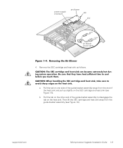
power supply enclosure
air blower tab
slot
air blower power cable
)LJXUH 5HPRYLQJ WKH $LU ...guide-bracket assembly to disengage the tab on the heat sink. Then lift the SEC cartridge and heat sink away from the guide-bracket assembly (see Figure 1-5).
support.dell.com
DELL CONFIDENTIAL - Preliminary 9/11/00
Microprocessor Upgrade Installation Guide...
Microprocessor
Upgrade Installation Guide - Page 14
(Rev. 11/3/98) FILE LOCATION: S:\SYSTEMS\SlimFast\ts\ProcUpgrade\028WD\028wdeb0.fm
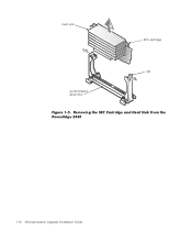
heat sink
SEC cartridge
tab
guide-bracket assembly
)LJXUH 5HPRYLQJ WKH 6(& &DUWULGJH DQG +HDW 6LQN )URP WKH 3RZHU(GJH
DELL CONFIDENTIAL - Preliminary 9/11/00
1-10 Microprocessor Upgrade Installation Guide
Microprocessor
Upgrade Installation Guide - Page 15
... air blower housing assembly, if it was removed in step 3 of the previous procedure.
3. Replace the system cover. 4. Reconnect your system and peripherals to their power sources.
support.dell.com
DELL CONFIDENTIAL - Preliminary 9/11/00
Microprocessor Upgrade Installation Guide 1-11
Microprocessor
Upgrade Installation Guide - Page 16
... within an SEC cartridge and heat sink assembly. The system board has two guide-bracket assemblies, which hold the SEC cartridge and heat sink assemblies. If your ...RI WKH PLFURSURFHVVRU IRU XVH DV D VHFRQGDU\ PLFURSURFHVVRU
5HPRYLQJ D 7HUPLQDWRU &DUG
To remove a terminator card, perform the following steps. :$51,1*
%HIRUH \RX SHUIRUP WKLV SURFHGXUH \RX PXVW WXUQ RII WKH...
Microprocessor
Upgrade Installation Guide - Page 18
... assembly. 6. Slide the terminator card out of the guide-bracket assembly.
,QVWDOOLQJ D 7HUPLQDWRU &DUG
To install a terminator card in the guide-bracket assembly, perform the following steps: 1. Slide the terminator card into the guide-bracket assembly until the edge connec-
tor on the terminator card is firmly seated in the connector on the system board. 2. Place the retention clips...
Microprocessor
Upgrade Installation Guide - Page 19
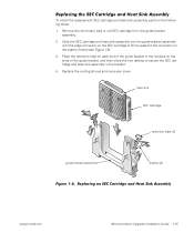
...system board (see Figure 1-8). 3. Place the retention clips on each end of the guide bracket in the notches on the ends of the guide bracket...computer cover.
heat sink
SEC cartridge
retention clips (2)
guide bracket assembly
latches (2)
)LJXUH 5HSODFLQJ DQ 6(& &DUWULGJH DQG +HDW 6LQN $VVHPEO\
support.dell.com
DELL CONFIDENTIAL - Preliminary 9/11/00
Microprocessor Upgrade Installation Guide...
Information Update - Page 1
This document updates information contained in your Dell PowerEdge 4400 system documentation.
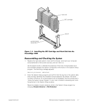
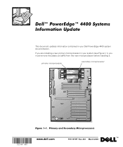
If you are installing a new primary microprocessor in your system (see Figure 1-1), you must remove the plastic air baffle from the new microprocessor before installing it.
primary microprocessor
secondary microprocessor
www.dell.com
P/N 15YHF Rev. A01 March 2000
™
Information Update - Page 2
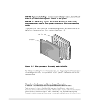
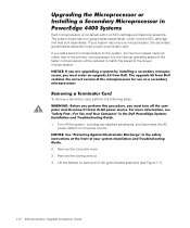
..., see "Upgrading the Microprocessor or Installing a Secondary Microprocessor" in your system's Installation and Troubleshooting Guide.
Information in this document is subject to change without notice. © 2000 Dell Computer Corporation. All rights reserved. Printed in the U.S.A. Trademarks used in this text: Dell, the DELL logo, and PowerEdge are trademarks of Dell Computer Corporation. Other...
RAID Memory Update - Page 1
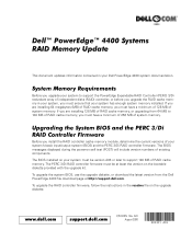
... BIOS installed on your system must be version A03 or later to support 128 MB of RAID cache memory. The PERC 3/Di RAID controller firmware must be at least the version on the bootable diskette provided with the upgrade kit.
To upgrade the system BIOS, use the upgrade diskette, or download the latest version from the Dell PowerEdge 4400 file download page at http://support.dell.com.
To upgrade the...
RAID Memory Update - Page 2
... firmware may cause other components to malfunction.
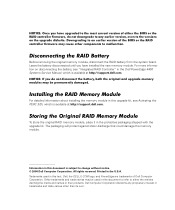
Disconnecting the RAID Battery
Before removing the original memory module, disconnect the RAID battery from the system board. Leave the battery disconnected until you have installed the new memory module. For more information on disconnecting the battery, see "Integrated RAID Controller" in the Dell PowerEdge 4400 Systems Service Manual...
Activating the PERC 3/Di - Page 9
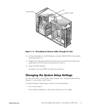
... the Battery Cable Through the Clip
10. Connect the battery to the RAID battery connector (RAID_BTRY) on the system board (see Figure 1-1).
11. Replace the cooling shroud and computer cover; reconnect the computer and peripherals to their AC power sources and turn them on.
12. Install the RAID software. For details, refer to the RAID controller documentation.
Changing the System Setup Settings
For...