Dell PowerEdge 6300 driver and firmware

Related Dell PowerEdge 6300 Manual Pages
Download the free PDF manual for Dell PowerEdge 6300 and other Dell manuals at ManualOwl.com
Replacing Dell PowerEdge 6300 and 4300 System Power Supplies - Page 1

...updates the power supply replacement procedure described in the Installation and Troubleshooting Guides for the PowerEdge 6300 and 4300 systems. The new power supply uses an improved method of engaging and disengaging the power... removed the existing power supply from your chassis. See your Installation and Troubleshooting Guide for instructions on how to remove the existing power supply. :$51,1*
...
Dell PowerEdge 6300 and 4300 Systems 1 x 2 Backplane
Installation Information - Page 1
...x 2 small computer system interface (SCSI) backplane for the Dell PowerEdge 6300 and 4300 systems. The 1 x 2 SCSI backplane provides hot-pluggable Ultra2/low voltage differential (LVD) SCSI connections for two 1-inch hard-disk drives in the system’s peripheral drive bay. For a description of the SCSI backplane’s functionality, see your system’s User’s Guide and Installation and...
Dell PowerEdge 6300 and 4300 Systems 1 x 2 Backplane
Installation Information - Page 2
... the system because the cord and cable connections in the system may become loose or damaged.
NOTE: If a cord or cable prevents the removal of a peripheral device from the system, unplug the cord or cable from the back of the peripheral device while it is still in the peripheral bay.
2 Dell PowerEdge 6300 and 4300 Systems 1 x 2 Backplane Installation Information
Dell PowerEdge 6300 and 4300 Systems 1 x 2 Backplane
Installation Information - Page 3
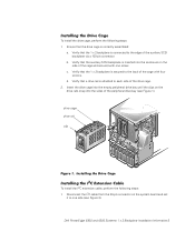
... the sides of the peripheral drive bay (see Figure 1).
drive cage drive rail clip
)LJXUH,QVWDOOLQJWKH'ULYH&DJH
,QVWDOOLQJWKH,&([WHQVLRQ&DEOH
To install the I2C extension cable, perform the following steps: 1. Disconnect the I2C cable from the 20-pin connector on the system board and set
it to one side (see Figure 2).
Dell PowerEdge 6300 and 4300 Systems 1 x 2 Backplane...
Dell PowerEdge 6300 and 4300 Systems 1 x 2 Backplane
Installation Information - Page 4
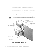
... cable is the standard cable found on all systems and provides power to peripherals; for example, for a CD-ROM drive or tape drive.
10-pin connector on 1 x 2 backplane
I2C extension cable
power connector
20-pin connector on system board
hard-disk drive SCSI backplane
I2C cable )LJXUH,QVWDOOLQJWKH, &([WHQVLRQ&DEOH
4 Dell PowerEdge 6300 and 4300 Systems 1 x 2 Backplane Installation...
Dell PowerEdge 6300 and 4300 Systems 1 x 2 Backplane
Installation Information - Page 5
... steps:
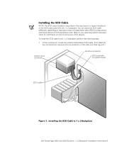
1. In the customer kit, locate the nonterminated 68-pin SCSI cable. (This cable has two connectors at one end and one connector on the other end. See Figure 3.)
bottom drive connector
top drive connector
SCSI controller on system board
SCSI cable
)LJXUH,QVWDOOLQJWKH6&6,&DEOHWR[%DFNSODQH Dell PowerEdge 6300 and 4300 Systems 1 x 2 Backplane Installation Information5
Dell PowerEdge 6300 and 4300 Systems 1 x 2 Backplane
Installation Information - Page 6
... away from the carrier. After you have installed your 1 x 2 backplane, see “Installing and Removing SCSI Hard-Disk Drives” in Chapter 10 of the Installation and Troubleshooting Guide for information on how to install your hard-disk drives. NOTE: The 1 x 2 backplane sets the top drive to SCSI ID0 and the bottom drive to SCSI ID1.
6 Dell PowerEdge 6300 and 4300 Systems 1 x 2 Backplane...
Installing a Microprocessor or Terminator Card - Page 1
™
Dell™ PowerEdge™ 63xx Systems INSTALLING A MICROPROCESSOR
OR TERMINATOR CARD
www.dell.com
Installing a Microprocessor or Terminator Card - Page 3

..., which can cause bodily harm. Only trained service technicians are authorized to remove the computer cover and access any of the components inside the computer. For more information, see "Safety Instructions" in your system's Installation and Troubleshooting Guide.
This document updates information contained in your Dell PowerEdge system documentation. The guide-bracket assemblies, which hold the...
Installing a Microprocessor or Terminator Card - Page 4
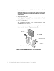
... attached peripherals, and disconnect the AC power cable from its power source.
NOTICE: See "Protecting Against Electrostatic Discharge" in the safety instructions at the front of your computer's Installation and Troubleshooting Guide.
2. Remove the computer cover.
See "Checking Inside the Computer" in your system's Installation and Troubleshooting Guide for more information.
3. Remove the cooling...
Installing a Microprocessor or Terminator Card - Page 5
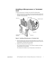
... latches to secure the microprocessor or terminator card in the bracket.
3. Replace the cooling shroud and computer cover.
See "Checking Inside the Computer" in your system's Installation and Troubleshooting Guide for more information.
This completes the installation of your microprocessor or terminator card.
support.dell.com
Dell PowerEdge 63xx Systems-Installing a Microprocessor or Terminator...