Epson PowerLite S3 driver and firmware


Related Epson PowerLite S3 Manual Pages
Download the free PDF manual for Epson PowerLite S3 and other Epson manuals at ManualOwl.com
ESC/VP Level 21 Communication Manual - Page 1
...", please do not utilize this downloading service.
LICENSE AGREEMENT
1. Copyright of "ESC/VP21 Command User's Guide" (hereafter referred to as user's guide) is owned by SEIKO EPSON Corporation (hereinafter referred to as EPSON). EPSON grants you to print out and use only 1 set of the user's guide only for the purpose of using the EPSON projector. You may not duplicate, reprint...
Installation Guide - ELPMBUNI Universal Mount Assembly - Page 2
... TO THE IMPLIED WARRANTIES OF MERCHANTABILITY AND FITNESS FOR A PARTICULAR PURPOSE.
Contact Premier Mounts
In the event of missing and/or damage equipment, or technical questions, the following information can help in the completion of the installation.
Customer Service - (800) 368-9700 Technical Support - [email protected]
Installation Instructions
Page - 3 -
Installation Guide - ELPMBUNI Universal Mount Assembly - Page 3
.... KEEP THESE INSTALLATION
INSTRUCTIONS IN AN EASILY ACCESSIBLE LOCATION FOR FUTURE
REFERENCE.
Indicates that the power plug is to be disconnected from the power outlet.
Contact Premier Mounts with any questions - (800) 368-9700.
Safety precautions must be taken at all times.
Warning and Caution statements.
A secure structure must support the weight, or load, of the projector. When...
Installation Guide - ELPMBUNI Universal Mount Assembly - Page 4
... 4)
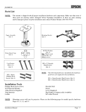
Installation Tools
Phillips Head Screw Driver Soft Material...installation.
M5 x 12mm Security Head Screws (Qty 4) M6 x 12mm Security Head Screws (Qty 4)
Portable Drill Pencil Level (Supplied) Stud Finder (Commercially Available) M5 Allen Wrench
NOTE: Mounting screws will vary by projector. Please see the following pages for model specific hardware: Pages 10, 11, 12, and 13.
Installation Manual...
Installation Guide - ELPMBUNI Universal Mount Assembly - Page 5
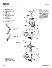
... Adjustment Screws F Tension Knobs G Safety Knob H Security Screws I Leveling Barrels J Universal Mounting Bracket K Leg Assembly L Projector (Not Supplied) M Tri-Lock Opening
Option 1 H
B D F
Combination
I
Leg
Single Leg
D Option 2
M
NOTE: See the best configuration...depending on the
number of mounting points
found on the bottom of your
G
projector.
K
M J
L
J
L
Installation Manual
Installation Guide - ELPMBUNI Universal Mount Assembly - Page 6
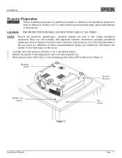
... could result in serious personal injury and possible damage to the projector.
CAUTION: THE PROJECTOR IS FRAGILE; HANDLE WITH CARE AT ALL TIMES.
NOTE:
Review the projectors manufacture's operation manual and refer to the ceiling installation instruction. Here you will normally find important reference information regarding installation dimensions such as (distance from the screen to the lens...
Installation Guide - ELPMBUNI Universal Mount Assembly - Page 7
ELPMBUNI
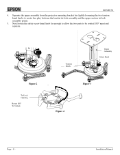
4. Separate the upper assembly from the projector mounting bracket by slightly loosening the two tension knurl knobs to create free play between the bracket tri-lock assembly and the upper section tri... be rotated 180° apart and separate.
Figure 2
Tri-Lock Opening Rotate 180° To Unlock
Tension Knobs
Upper Assembly
Safety Knob
Figure 3
Figure 4
Page - 8 -
Installation Manual
Installation Guide - ELPMBUNI Universal Mount Assembly - Page 8
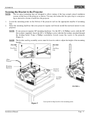
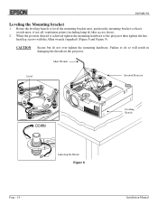
... screwdriver, loosely secure the screws to the projector (Figure A).
NOTE: The levelers and leg assembly screws must be loose in order to adjust the height of the mounting bracket.
FIGURE 6
Two-Piece Leg
FIGURE 7 One-Piece Leg
Allen Wrench
Mounting Hardware
Inverted Projector
Leveling Barrels
FIGURE A
Installation Manual
Figure 5
Line up the leveling barrels...
Installation Guide - ELPMBUNI Universal Mount Assembly - Page 9
ELPMBUNI
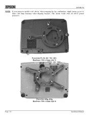
NOTE: If your projector model is not shown, when arranging the leg combination, simply ensure access to filters and lamp housings when aligning brackets. This mount works with all sub-25 pound projectors.
PowerLite S3, S4, 62C, 76C, 82C, Hardware: M4 x 12mm (Qty 3)
Page - 10 -
PowerLite 830p, 835p Hardware: M4 x 12mm (Qty 4)
Installation Manual
Installation Guide - ELPMBUNI Universal Mount Assembly - Page 10
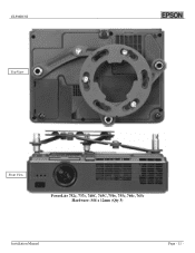
ELPMBUNI Top View
Front View
PowerLite 732c, 737c, 740C, 745C, 750c, 755c, 760c, 765c Hardware: M4 x 12mm (Qty 3)
Installation Manual
Page - 11 -
Installation Guide - ELPMBUNI Universal Mount Assembly - Page 13
... lamp & filter access doors).
2. When the position desired is achieved tighten the mounting hardware to the projector then tighten the hex head leg screws with the Allen wrench (supplied) (Figure 8 and Figure 9).... will result in damaging the threads in the projector.
Allen Wrench
Level
Inverted Projector
DOWN
UP
Adjusting the Mount
Figure 8
Leveling Barrels
Page - 14 -
Installation Manual
Installation Guide - ELPMBUNI Universal Mount Assembly - Page 14
... will safely support the weight of the projector.
NOTE: Make sure to measure from the center of the mounting bracket to the front edge of the lens to determine the proper placement of the center of the upper assembly.
NOTE: If installing the security kit (ELPMBSEC), please refer to the security kit installation guide before...
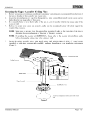
Installation Guide - ELPMBUNI Universal Mount Assembly - Page 15
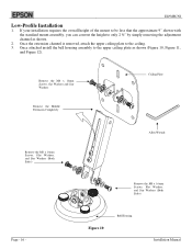
... the adjustment channel as shown.
2. Once the extension channel is removed, attach the upper ceiling plate to the ceiling. 3. Once attached install the bell housing assembly to the upper ceiling plate as shown (Figure 10, Figure 11,
and Figure 12).
Remove the M8 x 16mm... the M8 x 16mm Screws, Flat Washers, and Star Washers (Both Sides)
Page - 16 -
Figure 10
Bell Housing
Installation Manual
Installation Guide - ELPMBUNI Universal Mount Assembly - Page 16
ELPMBUNI
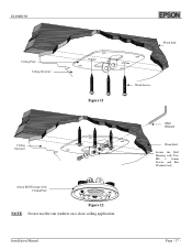
Ceiling Plate Ceiling Structure
Wood Stud
Figure 11
Wood Screws
Ceiling Structure
Attach Bell Housing to the Ceiling Plate
Figure 12 NOTE: Do not use the star washers on a close ceiling application.
Allen Wrench
Wood Stud
Secure the Bell Housing with Two M8 x 16mm Screws and Flat Washers Only
Installation Manual
Page - 17 -
Installation Guide - ELPMBUNI Universal Mount Assembly - Page 17
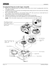
...slot on the mounting bracket (Figure 13).
NOTE: Follow the number sequence prior to securing the projector to the upper assembly.
The alignment slot must be in direct alignment with the safety knob to ...to the tri-lock, then rotate the projector 180°
Universal Mount
Page - 18 -
Safety Knurl Knob
Tension Knurl Knobs
Figure 13
Tri-Lock Opening Alignment Slot
Projector Mount
Installation Manual
Installation Guide - ELPMBUNI Universal Mount Assembly - Page 18
ELPMBUNI
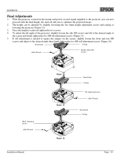
Final Adjustments
1. With the projector secured in the mount and power on and signal supplied to the projector you can now proceed with the final height, tilt, and roll ... Stud
Ceiling
Allen Wrench
Height Adjustable Screws
(Roll) Adjusting Screws Allen Wrench
Installation Manual
Figure 14 Figure 15
Wood Stud Ceiling
Tilt Adjusting Screws Allen Wrench
Wood Stud Ceiling
Figure 16
Page - ...
Installation Guide - ELPMBUNI Universal Mount Assembly - Page 19
ELPMBUNI
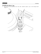
Installing the Plastic Caps
1. Once all the final adjustments have been done, install the plastic caps on the leveling barrels (Figure 17).
Figure 17
Page - 20 -
Installation Manual
Start Here Card - Page 5

... on the projector remote control repeatedly to move through the options.
See your User's Guide on the CD-ROM for more information about image adjustments.
Color Mode button
6 Install your User's Guide
and register your projector
1 Insert the CD-ROM in your drive. If the installer doesn't open
automatically, double-click the Epson CD-ROM icon, then double-click the Epson installer icon.
2 Choose...
User Manual - Page 26
...
• The USB cable can only be connected to computers with a standard USB interface. If using a computer which is running Windows, the computer must have had a full version of Windows 98/2000/Me/XP Home Edition/XP Professional installed. If the computer is running a version of Windows 98/2000/Me/XP Home Edition/XP Professional that has been upgraded from an earlier version of Windows, correct...
User Manual - Page 78

... serial number be removed or should the product fail to be properly maintained or fail to function properly as a result of misuse, abuse, improper installation, neglect, improper shipping, damage caused by
disasters such as fire, flood, and lightning, improper electrical current, software problems, interaction with non-EPSON products, or service other than by an EPSON Authorized Servicer...