Dell OptiPlex GX200 driver and firmware
Related Dell OptiPlex GX200 Manual Pages
Download the free PDF manual for Dell OptiPlex GX200 and other Dell manuals at ManualOwl.com
Service Manual - Page 2
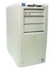
...Dell™ OptiPlex™ GX200 Systems Service Manual
Overview Recommended Tools Precautionary Measures Internal Views Computer Cover Eject, Power, and Reset Buttons Front-Panel Inserts Control Panel Chassis Intrusion Switch Drives
System Power Supply Expansion-Card Cage Riser Boards System Board Components Expansion Cards Memory...head screwdrivers l 1/4-inch nut driver Also, use a wrist ...
Service Manual - Page 5
... an integrated audio controller, be sure that the Sound setting is On. If the system has an audio expansion card, be sure that the Sound setting is Off. 5. While in System Setup, perform the following steps to configure the system if it has an LS-120 SuperDisk drive: a. Set Diskette Drive A and Diskette Drive B to Not Installed. b. Set Secondary Drive 0 or Secondary Drive 1, as appropriate...
Service Manual - Page 6
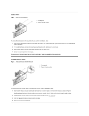
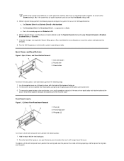
... steps: 1. Disconnect the control panel cable from the PANEL connector on the system board (see "System Board Labels" for the location of the PANEL connector). 2. From inside the chassis, remove the mounting screw that secures the control panel to the chassis. 3. Disconnect the chassis intrusion switch cable connector from the control panel. 4. Remove the control panel from the...
Service Manual - Page 7
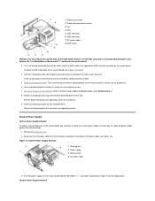
... Hard-disk drive 4 Chassis intrusion switch
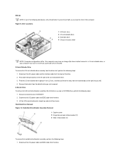
NOTE: Computer configurations differ. Your computer may have an Iomega Zip drive installed instead of a 3.5-inch diskette drive, or your computer may have no externally accessible drives installed. 3.5-Inch Diskette Drive To remove the 3.5-inch diskette drive assembly from the drive shelf, perform the following steps: 1. Disconnect the DC power cable and...
Service Manual - Page 8
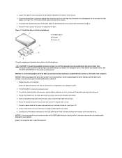
... with a screw. 7. Connect a power cable to the power input connector on the back of the drive (see Figure 12). 8. Check all connectors to ensure that they are properly cabled and firmly seated. 9. Connect one of the device connectors on the EIDE cable to the 40-pin interface connector on the back of the hard-disk drive. NOTICE: You must...
Service Manual - Page 9
... Setup, update the appropriate Primary Drive option, 0 or 1 (see the online System
User's Guide for complete information). 13. Partition and logically format your drive before you proceed to the next step.
See the documentation for your operating system for instructions. 14. If the drive you just installed is the primary drive, install your operating system on the hard-disk drive.
For instructions...
Service Manual - Page 11
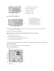
.... PCI/ISA Riser Board (Optional)
1 Auxiliary power indicator LED (AUX_LED) 2 Wakeup On LAN (WOL) connector 3 PCI expansion slot 1 (PCI1) 4 PCI expansion slot 2 (PCI2) 5 PCI expansion slot 3 (PCI3)
1 Auxiliary power LED (AUX_LED) 2 ISA expansion-card connector 1 (ISA1) 3 ISA expansion-card connector 2 (ISA2) 4 Remote Wakeup header (WOL) 5 PCI expansion-card connector 1 (PCI1) 6 PCI expansion-card...
Service Manual - Page 13
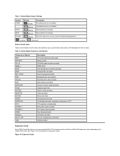
... fan connector Hard-disk drive LED connector EIDE interface connector Chassis intrusion switch connector Keyboard connector Modem audio connector Video connector Mouse connector Control panel connector Parallel port connector; sometimes referred to as LPT1 PCI expansion-card connector Main power input connector 3.3-V power input connector Riser board connector Serial port connector Primary...
Service Manual - Page 14
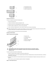
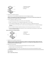
...system. The brackets also keep dust and dirt out of your computer. 6. Replace the computer cover and reset the chassis intrusion detector. Expansion-Card Installation Figure 20. Expansion-Card Installation
1 Expansion card 2 Card-edge connector 3 Riser board 4 Expansion-card connector 5 Expansion-card cage
CAUTION: Some network cards automatically start the system when they are connected. To guard...
Service Manual - Page 15
... in step 2. 5. Connect any cables that should be attached to the card.
See the documentation for the card for information about the card's cable connections. 6. Replace the computer cover and reset the chassis intrusion detector.
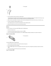
Memory To remove a Rambus in-line memory module (RIMM), perform the following steps:
1. Remove the computer cover. 2. Remove the system power supply to allow you...
Service Manual - Page 17
... pivot the release lever back toward the system board until it snaps into place, securing the microprocessor package.
Figure 26. Microprocessor Package Installation 1 Microprocessor 2 ZIF socket 3 Pin-1 (...computer cover and restart the system. c. Reset the chassis intrusion detector. While in System Setup, confirm that the system data area correctly identifies the type of microprocessor installed...
Service Manual - Page 18
...snap it into place.
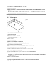
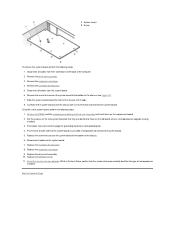
System Board Figure 28. System Board Removal
1 System board 2 Screw
To remove the system board, perform the following steps: 1. Disconnect all cables from their connectors at the back of the computer. 2. Remove the computer cover. 3. Remove the expansion-card cage. 4. Remove the 5.25-inch drive. 5. Disconnect all cables from the system board. 6. Remove the screw that secures...
Service Manual - Page 19
... and lock it into position (do not twist the system board). 5. Reconnect all cables to the system board. 6. Replace the 5.25-inch drive. 7. Replace the expansion-card cage. 8. Replace the computer cover. 9. Reset the chassis intrusion detector. While in System Setup, confirm that the system data area correctly identifies the type of
microprocessor installed.
Back to Contents Page
Service Manual - Page 21
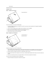
... of the way so that they do not catch on the computer cover. Make sure cables are not routed over the drive cage-they will prevent the cover from closing properly. 2. Facing the left side of the computer, hold the cover at a slight angle as shown in Figure 2. 3. Fit the three cover hooks into...
Service Manual - Page 27
... a bootable diskette into drive A, and turn on the computer system. 7. Reset the chassis intrusion detector. While in System Setup, update the Drive 0 option under Primary Drive n. 8. Partition and logically format your drive before proceeding to the next step.
See the documentation for your operating system for instructions. 9. Install your operating system on your hard-disk drive.
Refer to the...
Service Manual - Page 36
... following steps: 1. Remove the computer cover. 2. Disconnect all cables from the system board. 3. Rotate the system power supply out of the way. 4. Remove the RIMMs. 5. Remove the microprocessor. 6. Remove the AGP card brace and the AGP video card. 7. Slide all externally accessible drives and brackets partially out of the chassis. 8. Slide the hard-disk drive partially out of the...
Service Manual - Page 49
... for your operating system for instructions.
14. If the drive you just installed is the primary drive, install your operating system on the hard-disk drive.
For instructions, refer to the documentation that came with your operating system.
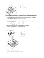
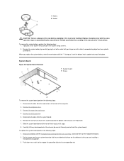
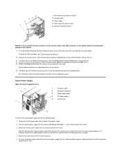
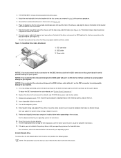
System Power Supply Figure 20. Power Supply Removal
1
AC power cable
2
AC power receptacle
3
Power supply cradle
4
DC power cables
5
Securing tab
To...
Service Manual - Page 60
... the system board). 5. Reconnect all cables to the system board. 6. Replace the airflow shroud. 7. Replace the expansion-card cage. 8. Rotate the power supply back into place (see Figure 20). 9. Replace the computer cover. 10. Reset the chassis intrusion detector. While in System Setup, confirm that the system data area correctly identifies the type of microprocessor
installed.
Back to...
Service Manual - Page 68
... system board, see "System Board Components."
10. Replace the drive shelf and connect the diskette and CD-ROM drive power and interface cables. 11. Replace the computer cover. Then reconnect your computer and peripherals to their electrical outlets, and turn them on. 12. Insert a bootable diskette into drive A. 13. Turn on the computer system. 14. Enter System Setup and update Primary Drive 0 (see...
Service Manual - Page 79
... bottom of the chassis. 6. Reconnect all cables to the system board. 7. Replace the hard-disk drive/bracket. 8. Replace the expansion-card cage. 9. Replace the drive shelf assembly.
10. Replace the computer cover. 11. Reset the chassis intrusion detector. While in System Setup, confirm that the system data area correctly identifies the type of microprocessor
installed.
Back to Contents Page