HP Indigo 7500 driver and firmware
Drivers and firmware downloads for this Hewlett-Packard item
Related HP Indigo 7500 Manual Pages
Download the free PDF manual for HP Indigo 7500 and other HP manuals at ManualOwl.com
Charge Roller -- CA393-00080 Rev 07 - Page 9
... cover
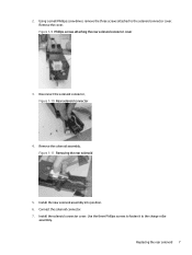
3. Disconnect the solenoid connector, Figure 1-10 Rear solenoid connector
4. Remove the solenoid assembly. Figure 1-11 Removing the rear solenoid
5. Install the new solenoid assembly into position. 6. Connect the solenoid connector. 7. Install the solenoid connector cover. Use the three Phillips screws to fasten it to the charge roller
assembly. Replacing the rear...
Charge Roller -- CA393-00080 Rev 07 - Page 11
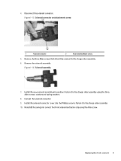
...solenoid to the charge roller assembly. 6. Remove the solenoid assembly.
Figure 1-16 Solenoid assembly
7. Install the new solenoid assembly into position. Fasten it to the charge roller assembly using the three ...Allen screws, washers and spring washers.
8. Connect the solenoid connector.
9. Install the solenoid connector cover. Use the Phillips screw to fasten it to the charge roller ...
Charge Roller -- CA393-00080 Rev 07 - Page 12

... instructions, and a notice of document confidentiality.
Revision history
Below is the history of the document revisions and a list of authors.
Revision
Description
CA393-00080 Rev00 Initial document
CA393-00080 Rev01 Updates
CA393-00080 Rev02 Add HP Indigo W7200 Digital Press to scope
CA393-00080 Rev03 Added the following press to scope: HP Indigo 7500 Digital Press, HP Indigo WS6000p...
IR Sensors Reading and Calibration -- CA393-09500 Rev 03 - Page 5
...the ITM
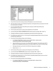
drum temperature to stabilize. 11. If you are using an IR scanner, set the IR scanner emissivity to 0.95. See the IR scanner
documentation if necessary. ... you cannot find a hardware failure, do the following:
a. In the System Table Editor window (not the SysTabIO Editor window), select irTempPropertiesTopic, blanketTempIROffset[0].
b. Apply the difference to the value in the offset field (...
Side Fog Troubleshooting - Page 11
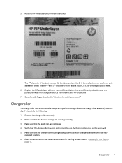
...Do not hold the PIP underlayer while inching as this might cause it to stretch.
2. When installing the PIP foil, make sure that the PIP underlayer is made partially wet with imaging oil on a lint-free ...wipe.
3. When installing the PIP foil, use only imaging oil on the PIP foil trailing edge to prevent it from loosening...
Side Fog Troubleshooting - Page 12
... batch, that is, a different production year or a production week with a large difference from the installed PIP underlayer. 7. Check for side fog as described in "Checking for side fog on page 1" ... assembly. 2. Make sure that the housing springs are working correctly. 3. Make sure that the guide rails are not loose. 4. Verify that the charge roller housing rests completely on the three position...
Side Fog Troubleshooting - Page 14
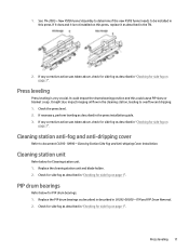
.... 1. Check the press level. 2. If necessary, perform leveling as described in the press installation guide. 3. If any corrective action was taken above, check for side fog as described in "...-dripping cover
Refer to document CA393-10990 - Cleaning Station Side Fog and Anti-dripping Cover Installation.
Cleaning station unit
Refer below for Cleaning station unit. 1. Replace the cleaning station unit...
Electrometer Board Test - Page 23
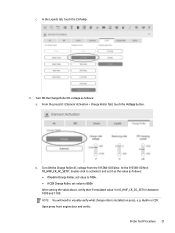
... as follows: ● If Hydrin Charge Roller, set value to 700v. ● If CCR Charge Roller, set value to 800v After setting the value above, verify that 'Formulated value' for IO_HVIF_CR_DC_SETV is between 1000 and 1100. NOTE: You will need to visually verify what charge roller is installed on press, e.g. Hydrin or CCR. Open...
Electrometer Board Test - Page 30
.... Updated Scope; Kit number and contents.
Responsible Engineer (TS) Press Group Manager DFE Group Manager R&D Engineer Engineering Documentation Manager Configuration Control Written...printer Duplex Full color Staple at top-left corner
Confidentiality notice
The information contained in this document is accurate at the date of release. Check Knowledge Zone on PrintOS for the most recent version...
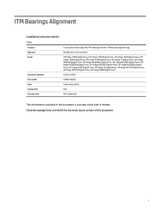
ITM Bearings Alignment - Page 1
...
Installation instruction details Table
Purpose Objective Scope
Document Number Kit number Date Related ECO Security level
To describe how to align the ITM bearings with the ITM bearing alignment jig.
Modification recommended
HP Indigo 7000 Digital Press, HP Indigo 7500 Digital Press, HP Indigo 7600 Digital Press, HP Indigo 7800 Digital Press, HP Indigo 7900 Digital Press, HP Indigo 7r Digital...
ITM Bearings Alignment - Page 2

... Estimated installation time ...2 Special skills ...2 Special jigs and tools ...2
2 Verifying the press leveling for HP Indigo 7000 Digital Press and HP Indigo 7500 Digital Press 3 3 Verifying the press leveling for HP Indigo WS6000 Digital Press and HP Indigo W7200 Digital Press ... and confidentiality notice ...39 Revision History...39 Printing instructions ...39 Confidentiality notice...40
ii
ITM Bearings Alignment - Page 4
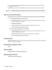
... for HP Indigo 7000 Digital Press and HP
Indigo 7500 Digital Press on page 3". b. Follow the instructions in "Removing press components for access on page 6". c. Do the remaining procedures in this document.
Prerequisites
Follow the instructions in "Verifying the press leveling for HP Indigo 7000 Digital Press and HP Indigo 7500 Digital Press on page 3" on page 5.
Estimated installation time...
Production Handbook for Indigo 7000 Series Digital PressesTo format this PDF see Q:\Technical writers\Procedures\Cheetah\How-to - Page 11
...Update ...Measure 3 gray levels (digital 6%, 14%, 40%)...software searches for the end of job). ● Manual...Powered by Esko. ● The eye is the most sensitive tool for comparing colors. Be aware that colors may look the same under one light source but differ under another light source. Therefore, use the same lighting in the pressroom as in the proof-checking area. ● HP Indigo Solids Optical...
Production Handbook for Indigo 7000 Series Digital PressesTo format this PDF see Q:\Technical writers\Procedures\Cheetah\How-to - Page 14
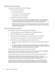
...3. The Start screen of the wizard displays the method to be used to run...install a new type of substrate in the software and on the press, activate the Create Media Fingerprint option from the Substrate Properties screen, Color Control tab. After the press detects that a new type of substrate was installed... the Color Automation package is installed) - A short version of the Media Fingerprint process,...
Impression Drum Service -- CA393-04641 Rev 02 - Page 3
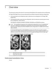
... impression drum and bearing configurations are not compatible with each other. Upgrading the old bearings configuration to the new requires replacement of the impression drum. Spare parts will be available for both configurations. For additional information, refer to TN-1493. In HP Indigo 7500 Digital Press P/N 43000205 and above, the GDU motor has been changed...
Impression Drum Service -- CA393-04641 Rev 02 - Page 6
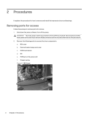
... and install the impression drum and bearings.
Removing parts for access
Follow these steps to remove parts for access. 1. Shut down the press software. Turn off the press.
WARNING! The main power switch must remain off, the UPS must remain disconnected, and the main power at the wall must remain off/disconnected until instructed otherwise...
Impression Drum Service -- CA393-04641 Rev 02 - Page 46
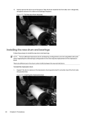
... and bearing configurations are not compatible with each other. Upgrading the old bearings configuration to the new requires replacement of the impression drum. There are differences in the drum center shafts between the new and old drum. To install the impression drum: 1. Support the drum in place on the impression drum jig and...
Impression Drum Service -- CA393-04641 Rev 02 - Page 60
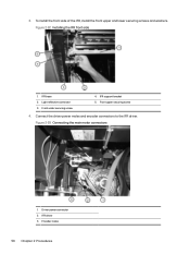
... screws and washers. Figure 2-92 Installing the IFR front side
1. IFR base 2. Light reflective connector 3. Front under securing screw
4. IFR support bracket 5. Front upper securing screw
4. Connect the driver power molex and encoder connectors to the IFR driver. Figure 2-93 Connecting the main motor connectors
1. Driver power connector 2. IFR driver 3. Encoder molex
58 Chapter 2 Procedures
Impression Drum Service -- CA393-04641 Rev 02 - Page 63
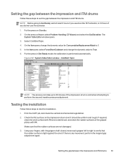
... press on Standby. 2. On the press software, select Problem Handling, CE Wizard, and select the SysTab editor. The
System Table Editor window opens. 3. Select ColdStartTopic. 4. On the...to perform the second transfer pressure adjustment.
Testing the installation
Follow these steps to test the installation. 1. Print the CATP job, and check the ...Setting the gap between the impression and ITM drums 61
Front-to-Back FTB Troubleshooting - Page 5
... definitions) If the image placement moves in the wrong direction in the Job Properties screen: For SW V11.2 Upgrade to SW V11.4 or Request Image Placement Plug-in 11.2 from the WWTS Software PM (yaron.gazit@hp.com) For DFE V5.1, request discrete fix DF103 from the WWTS Production Pro PM (brett.bates...